Product Description
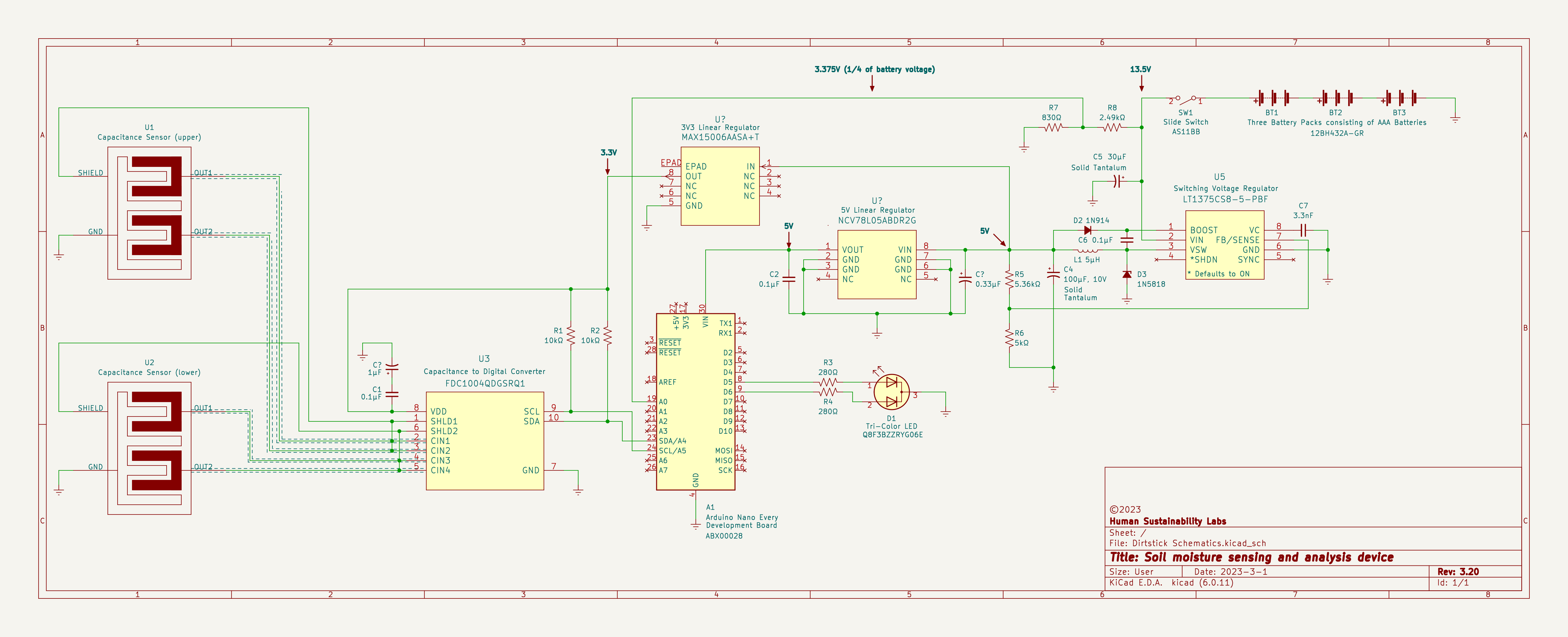
The device is a soil moisture sensing and analysis device that uses capacitance sensing technology to help manage soil moisture in your garden. One probe set at the bottom of the device and a second probe set just under the soil line, allow the device to measure soil moisture across the full vertical profile of the soil. Analysis of the data determines if the soil is over-saturated, optimally-saturated, wilting, or dry.
Green, yellow and red, instantly recognized symbols for good, bad and in-between serve as the interface of the device. These colors are used to indicate four discrete levels of soil moisture, and a low battery warning. The device is powered by three 4.5 V battery packs for a total of 13.5 V, which will (when the development board is replaced with its Microchip) power the device for the entire growing season.
Schematic Comments
- The dashed lines indicate shielded cable.
- Any and all other comments on the schematic.
Sensor Design
Capacitive sensing is a technology, based on capacitive coupling, that can detect and measure anything that is conductive or has a dielectric constant different from air. Dielectric sensors measure the charge-storing capacity of the soil. This charge-storage approach is much more effective than a resistance approach. The ideal dielectric sensor electrical circuit is one that simply acts to polarize water molecules between two electrodes.
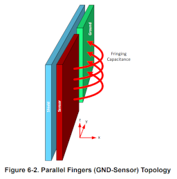
The parallel fingers (GND-sensor) topology works under the principle of fringing capacitance. High sensitivity along the z-axis of the sensors enables this topology to be implemented in liquid level sensing applications. The electric field lines are more dominant near the edges between the sensor and ground plates. The sensitivity of the sensors increases as sensor size increases (non-linearly). A shield on the backside of the main sensor and GND electrode provides directivity towards the soil.
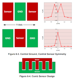
Multiple sensor and ground electrodes can be alternated to have a central ground or sensor symmetry, as shown in Figure 6-3. A central ground is required for a wide directivity along the width of the electrodes and gives the widest response. A central sensor electrode is required for high directivity along the width of the electrodes and provides the sharpest response. The comb configuration, as shown in Figure 6-4, is comprised of both of these variants and very effective for wide and high directivity.
Spin the Comb Design Around a Cylinder
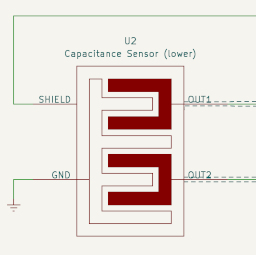
This is my spin on the comb configuration. what I have to accomplish, with your help, is the validation of the sensor design and form.
Starting with the equation for capacitance of a parallel plate capacitor:
$$C=\frac{\varepsilon_r\times \varepsilon_0 \times A}{d}$$
Where:
- \$A\$ is the area of the two plates (in meters)
- \$\varepsilon_r\$ is the dielectric constant of the material between the plates (cultivated soil is 15)
- \$\varepsilon_0\$ is the permittivity of free space (8.85 x 10⁻¹² F/m)
- \$d\$ is the separation between the plates (in meters)
Distance is the most obvious factor that needs to be reworked for my application. Given my cylindrical parallel fingers topology, how can I calculate capacitance?
Datasheets
Voltage Regulator
Voltage Reference
Development Board
Capacitance to Digital Converter
Tri-Color LED
References
Basics of Capacitive Sensing and Applications
Common Inductive and Capacitive Sensing Applications


