5
\$\begingroup\$

I want to make a circuit with a 555 timer to run 72 LEDs all at the same time. I have already made a circuit, but am not sure If it will work safe and long or not. I am putting the picture of the circuit and I want anybody who can help to look at it and see if it needs some extra components. Please add them on the circuit or explain instructions to add.

enter image description here

\$\endgroup\$
1
  • \$\begingroup\$ Where is the picture? \$\endgroup\$
    – ThomasW
    Commented Apr 17, 2013 at 5:20

2 Answers 2

12
\$\begingroup\$

Your proposed circuit will not work. Let's say a single three LED string draws 20mA, then 24 strings in parallel will draw 24 × 20mA = 480mA.

Now take a look at the datasheet for a typical 555. Although the maximum output current for the 555 is not explicitly mentioned, the 'Low Output Voltage' parameter on page 3 is only spec'd up to 200mA. This means the 555 will not be able to higher sink currents than that.

What you need is a driver stage, a transistor that can be controlled by the 555 and can drive the required current. Simplest is to use a MOSFET, which is perfectly viable with a 12V supply voltage. Because you didn't mention the exact LED current, I can't propose a transistor part number, but the circuit looks like this:
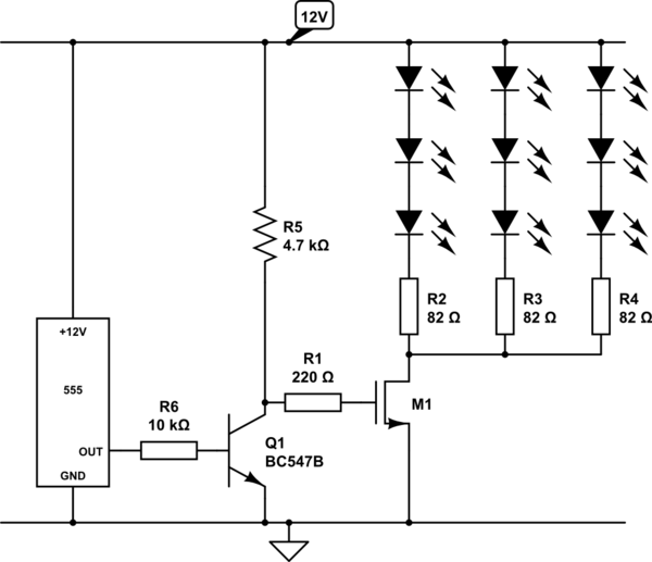
schematic

simulate this circuit – Schematic created using CircuitLab

Actually the below may work too, but I can't test it. The discharge pin is open collector and inverted from the output pin. The MOSFET again inverts the signal, hence the BJT from the circuit above can be eliminated.
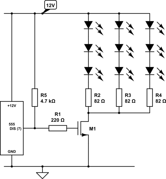
schematic

simulate this circuit

For selecting a proper transistor, look for I(D) being larger than the total expected LED current. Make sure you have some head room, maybe a factor 1.5 - 2 or more.

\$\endgroup\$
5
  • \$\begingroup\$ But now you need to somehow invert the polarity of the output of the 555 in order to get the same functionality. \$\endgroup\$
    – Dave Tweed
    Commented Apr 17, 2013 at 12:28
  • \$\begingroup\$ @DaveTweed Good point, I didn't notice it wasn't configured as astabile multivibrator. I changed the circuit with an extra inverter stage. \$\endgroup\$
    – jippie
    Commented Apr 17, 2013 at 14:00
  • \$\begingroup\$ I would use a little IGBT instead of the MOSFET \$\endgroup\$ Commented Dec 18, 2013 at 18:30
  • \$\begingroup\$ The maximum current of each LED line can be calculated from the source voltage (12V), minimum LED forward drop (3.2V) and current-limiting resistor value (82R) in OP's schematic: 12V - (3*3.2V) / 82 Ohms ~= 29mA \$\endgroup\$
    – cristoper
    Commented Dec 18, 2013 at 19:07
  • \$\begingroup\$ Better idea: divide the LEDs into, say, 8 groups, and use the 555 timer to generate a clock signal which drives some digital circuit (e.g. 8 bit shift register based thing) that rotates among the 8 groups. \$\endgroup\$
    – Kaz
    Commented Dec 18, 2013 at 19:46
2
\$\begingroup\$

You have 25 parallel LED circuits. With a 12v supply, 82 ohm resistors, and Vfwd on the LEDS of about 3.5v the current in each circuit will be about 20mA.

25 circuits at 20mA is 500mA

I think the maximum current from a 555 is 200mA.

This circuit is stressing the 555, it probably will stop working soon.

\$\endgroup\$

Your Answer

By clicking “Post Your Answer”, you agree to our terms of service and acknowledge you have read our privacy policy.

Not the answer you're looking for? Browse other questions tagged or ask your own question.