0
\$\begingroup\$

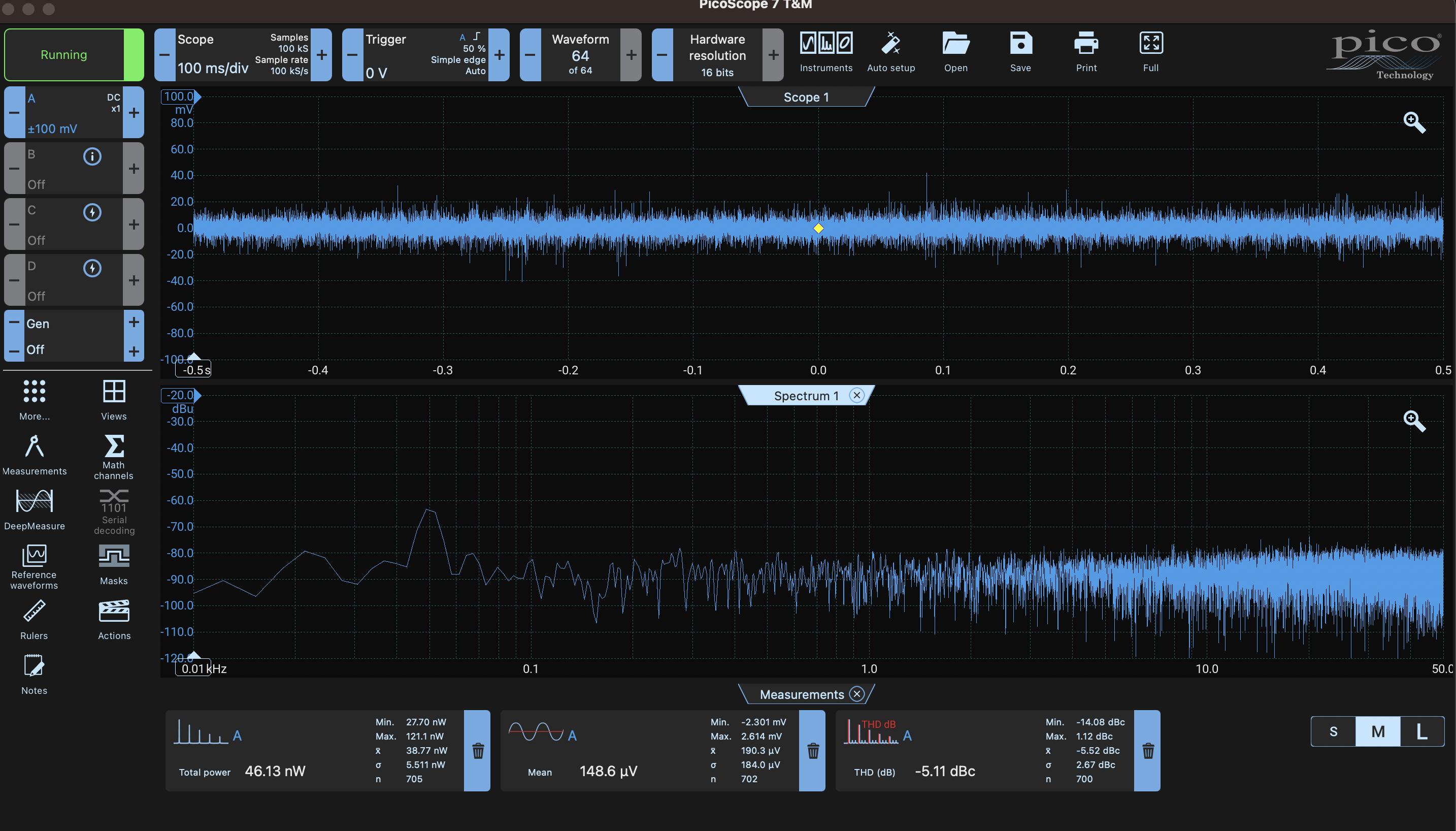
I'm using the following circuit to produce white noise. I'm applying 12V DC from a power supply. But my noise is very low - not at all amplified! I was expecting at least 100mV Vpp, but it's only about consistent 10mV Vpp.

From what I've seen from this link and this link I suppose it should be giving more amplification at the output than what I'm getting.

Is this the normal behavior of the circuit or am I missing something? What could I do to amplify the signal at the output without introducing op-amps (I was hoping T2 would gain a lot more)?

Thank you a lot!

I'm using 2N3904. But also tried with BC547 and BC3337. I also tried changing R1 to 48k ohms, with no result.

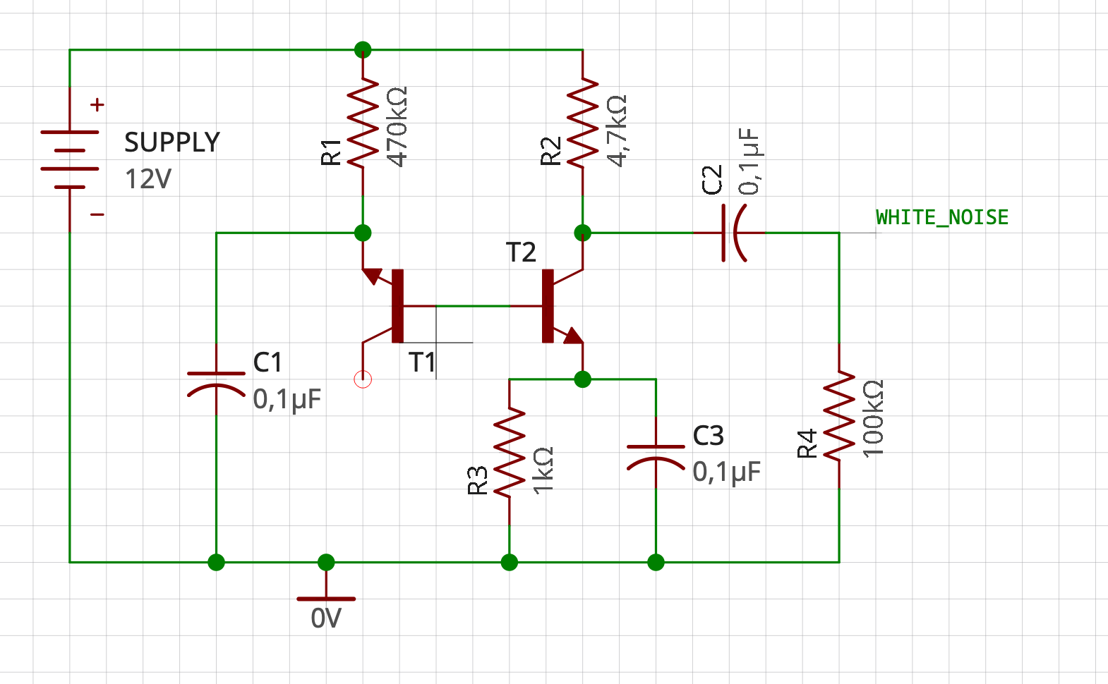
enter image description here

enter image description here

\$\endgroup\$
9
  • 1
    \$\begingroup\$ Can you show what the DC voltage level is at the collector of T2. Ideally, you want this to be about 6 volts. Relying on the breakdown of T1 to bias T2 the right amount is usually quite problematic. There are better ways. \$\endgroup\$
    – Andy aka
    Commented Mar 31, 2023 at 17:49
  • 1
    \$\begingroup\$ Before we get into any whys or wherefores -- I see you expected 100mV peak to peak. But -- over what frequency range? What transistors are you using, and what did the original article call out? Are you using bandlimiting on the scope, and is it different from what the original article used? \$\endgroup\$
    – TimWescott
    Commented Mar 31, 2023 at 17:51
  • \$\begingroup\$ I'm sorry @TimWescott, you are right. I edited the question to include the transistors I've tried. \$\endgroup\$
    – ludicrous
    Commented Mar 31, 2023 at 17:53
  • \$\begingroup\$ @Andyaka The voltage at the collector of T2 is around 9.5V. I put a resistor of 1M ohm instead of 4.7k ohm to bring it down but didn't do any effect to the output (still around 10mV Vpp) \$\endgroup\$
    – ludicrous
    Commented Mar 31, 2023 at 18:02
  • \$\begingroup\$ 9.5 volts is OK on a 12 volt supply. What's the scope show (noise wise) on the base of T2 compared to the proper output? \$\endgroup\$
    – Andy aka
    Commented Mar 31, 2023 at 18:03

1 Answer 1

1
\$\begingroup\$

The voltage at the collector of T2 is around 9.5V.

OK, so there's about 0.5mA flowing through Q2, and its emitter is at 0.5V. Q1's B-E Zener diode has about 12V-(0.5V+0.65V)=11V across it. That should be enough, but go for a 15V supply until it works better. It can't hurt.

Not all transistors will be equally noisy. 2N2222 was my go-to part for Zener noise generation. Maybe try that for Q1. An order of magnitude range in noise amplitude is normal between various types of transistors. I'd get one of those cheap transistor kits, and try various PNP and NPN types in reverse B-E breakdown. You'll see that some of them are much noisier than others.

I'd say the circuit works just fine with 10mV output noise amplitude. That's just what you get with the particular transistors you tried.

C2-R4 is not necessary for measurements. Remove those, add an emitter follower loaded with 33k, then hook that emitter up directly to a 10x scope probe, AC coupled channel.

Make sure the PicoScope is aware of the 10x probe you're using.

\$\endgroup\$

Your Answer

By clicking “Post Your Answer”, you agree to our terms of service and acknowledge you have read our privacy policy.

Not the answer you're looking for? Browse other questions tagged or ask your own question.