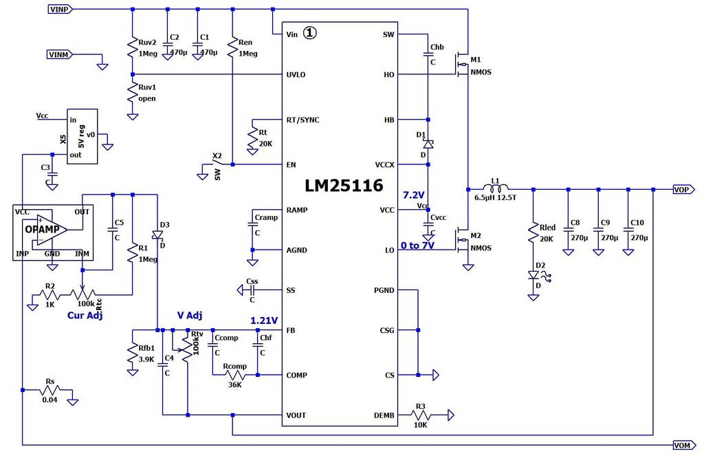
I have the popular SZBK07 DC-DC buck converter, which seems to have the following schematics:

The manufacturer gives the following parameters:
- Non-isolated, adjustable DC/DC buck (step down) constant-voltage or constant-current converter (supplies constant voltage until set current is reached, then constant current)
- Not reverse polarity protected
- Input/output voltage differential: 3 V min.
- Input voltage must be higher than required output voltage
- Input Voltage: DC 6-40 V (10 to 40 V is suggested)
- Output Voltage: DC 1.2-36 VDC
- Output Ripple: ~ 50 mV
- Rated Current: 15 A, 20 A max.
- NOTE: Wattage Limited 300 W max. (V x I x Eff. = W)
- Efficiency: 96% max (Nominal 86%
- Current Adj. (CC): sets the available charging/driving current
- Operating Temperature: -10°C to 75°C (Fan recommened if heatsink > 65°C)
- Working frequency: 150 kHz
My goal is to use this converter as a regulated constant-current source, which I need to control digitally. I will use it at a fixed input voltage of about 12 V. The output current range that I need is from the lowest possible up to about 7 A (it could be little bit higher if I can get a little bit higher voltage from the power source).
As can be seen from the schematics, the current control is executed in the following way: the voltage drop over the shunt Rs = 0.004 Ω (wrong value in the picture) is amplified by an op-amp (LM321) and the output voltage is fed through D3 to the FB input of the LM25116, where it is combined with the voltage from the voltage control circuit (Rfb1 - Rtv). So both control the same thing - the output voltage.
So my ideas to digitize the current control are:
Exchange Rtc with a digital 100kΩ potentiometer. The problem is that I cannot find such potentiometer available nearby, but I can find 10 kΩ. So the questions here are: Is there some general problem using a digital potentiometer? Can I decrease the values of R2, Rtc and R1 (for example 10 times) in order to use a 10kΩ potentiometer or to recalculate them to fit 10 kΩ in the range of control that I want?
In case there is some problem with the previous idea, I could remove D3, measure the output of the opamp with the microcontroller (10-bits ADC) and control the voltage Vadj with PWM or DAC. Any problems with this? Probably problems when the DAC or PWM outputs are not initialized yet?
Instead of using the op-amp output, I can measure the current with a Hall sensor and use it in the same way as in point 2.
Ideas and advice are highly appreciated.
