6
\$\begingroup\$

I am looking for a way to communicate without using a CPU on one side of the communication.

For more details, I have many cards that need to communicate with one main card on which there is a CPU. Right now, they are communicating without any protocols, just using analog signals. The problem is that it uses a lot of pins on my main card and I do not have that many available (this is not something I can change.)

The only solution I found to save some pins is to use a serial communication (I²C, RS-485, etc.) The problem is that I cannot use a CPU on the "slave cards" because of some safety reasons (it is also something that is specified so I cannot change it.) To be more precise, I cannot use anything that has memory.

Is there a communication protocol that does not need any kind of CPU (chips with memory) on the slave side to work? Can I use only analog circuitry to receive/send the data on the slave side? If there is not, do you have any other idea on how to save pins on the main card?

EDIT

I am adding details here because my first post was missing some.

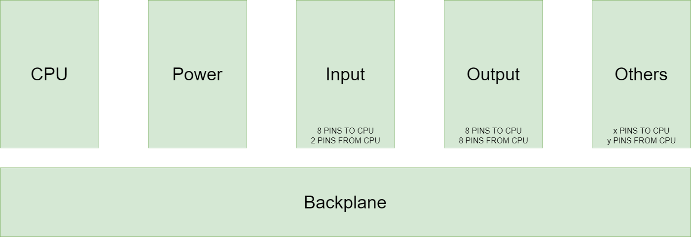
Schematic of the system

The system is made of one backplane and the user can plug the cards they want into it. Obviously the CPU and the power card will always be plugged in.

The thing that makes this system a bit difficult to conceive is the safety aspect. Each card has a way to check that it is working properly.

Here is an example of how the system is working right now:

  1. CPU: I am sending to Input a specific signal on its inputs (short-circuit). I am doing this so I can check if there is a problem with the Input card.
  2. Input: I am processing the signal (by processing, I mean filtering and other analog stuff but nothing digital) and sending it back.
  3. CPU: The signal is correct so I can consider that what the Input is reading and sending me is correct.
  4. Do the same stuff with Output or cards with sensors.

In this example, just for an input, we are using 4 different pins (IN+ & IN- that are being sent to CPU and IN+_Test & IN-_Test that are here to test the input card. So what I am trying to do is replace all those analog signals by a serial communication (half duplex or full duplex) to have more pins available on the CPU card.

I need to avoid memory stuff (every kind of memory) because there is always the possibility (even if small) that it remembers the specific signal that I am using to check if a card is correctly working. If that happens when there is a problem with a card, it could do something that was not intentional (the doors of a plane open but the plane is still flying for example). The CPU card is protected against this kind of problem but it costs a lot so I cannot do the same thing on the other cards.

Just for information: I know that things could be done on the software side but this is not what I want. I am only looking for hardware answers.

To be clear, for me what I am trying to do is impossible. I do not see how one can do serial communication without registers. But I am asking just to be sure.

\$\endgroup\$
21
  • 4
    \$\begingroup\$ Serial MUX, ADC, DAC etc. should be able to do what you request. \$\endgroup\$
    – Klas-Kenny
    Commented Apr 17, 2023 at 9:49
  • 11
    \$\begingroup\$ It's hard to know unless you give us an idea about what you're trying to communicate between the two boards, whether it's full duplex, what the slave boards need to do when they receive values and what you have on the slave boards to send intformation to the master. \$\endgroup\$
    – DiBosco
    Commented Apr 17, 2023 at 10:06
  • 6
    \$\begingroup\$ How strictly is "memory" defined? Does it only refer to non-volatile memory? Can you use devices containing flip-flops, such as shift registers, driven by a SPI-like (or JTAG-like) protocol? \$\endgroup\$
    – Dave Tweed
    Commented Apr 17, 2023 at 11:25
  • 6
    \$\begingroup\$ I'm confused about how digital memory is supposed to be more dangerous than the analog setup. You say you test the cards by short-circuiting their lines, then reading some signal from their output. But what happens if the lines are shorted by a piece of debris or something? Then the card will still send back the "all clear" signal, yet it has failed. \$\endgroup\$ Commented Apr 17, 2023 at 19:17
  • 15
    \$\begingroup\$ Re, "Any kind of memory is forbidden." That doesn't make sense. I think you need to have a discussion with whoever wrote that requirement. You can implement a serial protocol without a CPU (Don't ask me how I know!) You can implement it without megabytes of DRAM, you can do it without kilobytes of SRAM even, but you can't do it without some kind of memory. Even the simplest protocols have state at some level, and a state machine has to remember what state it is in. \$\endgroup\$ Commented Apr 18, 2023 at 2:24

9 Answers 9

39
\$\begingroup\$

First, I just want to emphasize something peculiar about the context here.

This is apparently a safety driven design, perhaps even a life-critical aerospace or medical application. We [readers and answerers] can safely assume that some kind of large price will be paid by failing these conditions. Maybe it won't meet with immediate consequences (say, the safety features were bypassed but the system continues to function as expected), but eventually consequences will come (system fails to function, then safety features fail to report this change accurately).

And "large" might merely be a matter of equipment or infrastructure costs (borne by the end customer, or your employer, or their insurance, as the case may be), or it may be multiple human lives. Which is still a cost -- even in the most bleak, realist, psychopathic economic terms, lives correspond to some millions of dollars each; depending on where they're located, of course.

Contrast this with where we are: the internet. Anyone, anywhere, relatively anonymously, can join and submit an answer here.

That's not to say you can't get good answers from the internet. And you might get poor answers, and they might be downvoted, it's true, there is such an identification mechanism here. But there's also a massive gulf between answers that look good enough to pass casual inspection and which aren't worth downvoting; and well-informed, responsible and accountable answers. Indeed, the latter tend not to be upvoted as much, simply because they are more difficult to assess.

So, beyond the most obvious cases, you are left with nothing but your own critical faculties to assess whether an answer is reasonable or not.

And, not to cast aspersions or anything, this is just my assumption, or opinion -- but given the discrepancy between the above facts, one would be right to question whether those faculties are adequate, given the weight of the task at hand.

As a result, I strongly urge you or your employer to see out a professional consultant skilled in the matter. A consultant (or employee, or whatever) won't be cheap, no. But they also won't cost lives, or future materials costs or lawsuits or insurance premiums.

Anyway, given the above; as another random agent of the internet, let me do my duty and offer dubious information, suitably steeped in varying amounts of helpfulness, over-seriousness, and sarcasm, that you may use at your own risk.


We can approach the basic problem ("shortage of pins on the CPU card", if I'm not mistaken) in several ways.

  1. If the signals are digital in nature (i.e. binary or other discrete levels), multiple can be assigned to a given pin (or pin pair, if everything is differential, as seems to be implied) by weighting them orthogonally. That is, say we have a termination resistor at the CPU card, and each peripheral card sources a current proportion to its state, times a factor related to its position or type. The resulting bus voltage is the sum of currents times the resistance: \$V = R \sum_i I_i = R \sum_i x_i c_i\$, where \$x\$ is the state variable (e.g., 0 or 1) and \$c\$ is the position current factor (e.g. \$2^n\$ times a reference current, for each \$n\$th card). This is simply the definition of positional numbers, and for the binary case, it reduces to a binary DAC. The base can be anything, of course, and it can even vary from card to card, as long as no combinations of codes are redundant (different states producing the same voltage). You may also want to error out on any "impossible" codes (gaps that are [should be] unreachable based on all possible states and the given weights).

    Whether your CPU is able (mechanically speaking, or per the standard) to read this signal without state (such as a SAR or S-D ADC uses), or in the presence of interference / noise, is a separate issue.

  2. If the signals are continuous in nature, and cannot be quantized to a digital value (or, to a reasonably small number of bits), they can be multiplexed in various ways.

    TDM (Time Division Multiplex) generates a sequence of timing pulses, and during the respective time slot, each respective card gates its signal onto a common bus. The CPU then reads each slot accordingly.

    This is a symbol*-serial communication mode, which, like any other serial mechanism, requires storing states. We can use a fairly simple cheat here: using a sample-and-hold module, store the analog voltage from each respective symbol on a capacitor. The values can then be read out continuously and in parallel. The downside is the stored value decays over time, so it needs to be read out within some time frame depending on acceptable error.

  3. They can also be frequency division multiplexed (FDM). Each signal is modulated onto a carrier signal, and multiple carriers are summed onto the bus. The CPU card then separates each signal by filtering, and uses a detector to recover the original signal. AM is the simplest mode, and indeed this was the method used for early telephone trunking. This is simultaneously a simple and complex method; simple to implement in concept (few transistors are strictly needed), but complex to implement reliably i.e. at low distortion with good isolation between channels (in particular, the filters can be quite precise, depending on how densely packed you need the channels to be). Digital radio methods can of course offer greater density (higher performance for fewer parts), but again may not be applicable here.

There are other methods as well (e.g. orthogonal codes (CDMA)), but they are more complex so I will not go into them here.

*A symbol is a fixed level on the line, for some period of time. At least, it is for a typical time-quantized communication medium. On a digital serial port, a symbol is binary 0/1, and the period is the bit time (1/baud). The signals could be multi-nary: for example, 100BASE-T Ethernet uses ternary; many long-haul and radio modulations use phase-amplitude constellations containing thousands of states (i.e. >10 bits) per symbol.


No[,] analog states are not prohibited [sic]

Then digital states are allowed.

We can apparently solve this issue by using a capacitor to store state, for example.

Suppose we charge a capacitor to some voltage. That voltage will decay over time (the same issue with the sample-and-hold mechanism above). Suppose we only need to know approximately one bit of information about this voltage.

Note that analog signals are continuously variable, but might not be very "informative", or might be noisy enough that not much information can be obtained from it. We can express this as an equivalent number of bits (ENOB), or entropy, or other measures. These are continuous measures -- ENOB needn't imply a fixed number of bits, but can be fractional as well. In this sense, we can have a variable amount of information known about the signal.

Note our input isn't digital, it's continuously variable and contains a potentially variable amount of information; we're just "crushing" it down to one bit of output, and making the assumption that this is all we need to know about the input.
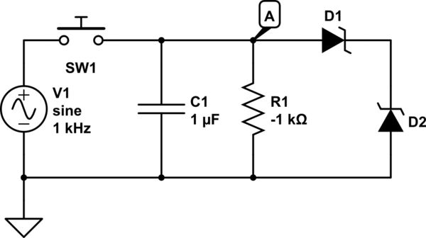
schematic

simulate this circuit – Schematic created using CircuitLab

To perform that "crushing", suppose we apply a negative resistance to the capacitor, and add clamp diodes so the voltage remains constrained between limits. (In practice, the negative resistance element has finite range already, but we can model it this way.) Now any voltage different from zero, will be amplified by the negative resistance, pushed towards the limits, and clamped by the respective diode. Any subsequent time we measure the capacitor, we find its voltage is as it was left, somewhere above or below zero; or after enough time, approaching or at the clamp voltage.

In this process, I have not specifically invoked an element of digital logic (a flip-flop), which would seem to be supported by the spirit of the standard as related here. But notice its output is fully digital: it has two stable well-defined output voltages, corresponding to an input within some bounded range (for input-high or input-low respectively). Have we therefore, in fact, constructed a digital memory? But how can that be, it is a continuous differential system (that is, we can express its behavior with a differential equation over continuous variables)!

Similarly, we can use analog states to construct counters, adders, etc. Analog computing is of course Turing-complete, assuming some means of expressing the expandable or unlimited memory requirement of a true Turing machine, of course.

For example, we can construct a counter using a current source into a capacitor: the voltage rises linearly with time. To get a digital sequence output, for example, simply use an array of comparators, and (combinatorial*) logic to resolve their outputs into windowed ranges; or a binary sequence, or whatever we like. (We can also use the same method (comparators and logic) to translate an analog signal into a binary representation while using no internal state: this is known as a "flash" ADC.)

Indeed, note that we can construct a SAR ADC this way, by storing acquired bits into a register S&H array, subtracting the difference (from the latest acquired bit value) from the input then doubling its scale (the input S&H capacitor's voltage is latched in recurrently from this subtract-and-scale function), and we've apparently never used "digital memory" in the process.

*Combinatorial logic (free of feedback loops) is stateless, so would seem acceptable here.

Perhaps we can even construct an SPI or I2C interface in this way!


But indeed, perhaps you are starting to see the problem here. There is a fundamental category error. Digital is not beside analog, it is a strict subset of analog. Indeed, no stipulation of the capacitor value, or the negative-resistance mechanism, is required of the above description of a "one bit" S&H, and digital logic solves this by using minimal capacitance (parasitic amounts) and pairs of transistors (as in SRAM and other flip-flops). So I've described sequential digital logic without having called it as such until here.

Whether this error is due to an incomplete description of the standard, or the standard itself is ill-conceived, I don't know.

It certainly isn't possible they mean to remove any state, as that's fundamentally impossible to a certain extent (EM fields around wires are indeed state, albeit very transiently so -- perhaps nanoseconds scale, unless carefully "gamed" to much longer time scales -- as in practical capacitor and inductor components), and a restriction on the amount of filtering for signal lines (filters are [analog] stateful!) would surely be counter to the root purpose of reliability.

It also seems unlikely that they would intentionally seek to prevent one of the most reliable tools available to engineers today: digital logic, used responsibly, offers truly minuscule bit error rates. A modern CPU, just by sheer nature of existence, without any special error-correcting functions (software asserts, error-correcting memory, redundant CPUs, etc.), incurs parts-per-trillion error rates! Now, while I would not stake my life on such a system (mainly because, not only is it performing billions of such calculations per second, but because the software that runs on it is incomprehensibly complex and not made to anywhere near the same standard as we're talking here), I would be more than confident using the few bits of digital logic that seems to be requested here.

It seems likely to me that a more nuanced description of the standard exists, which simply asks you not to abuse stored states on signals that must be read regularly, or indeed continuously (up to whatever their respective bandwidths are), so as to avoid data-redundancy and coherency errors (that is, the value read in one place, is supposed to equal the value in another place, but in fact differs because of some failure of the update mechanism). Whether this materially limits your implementation as far as the number of cards supported on the limited-pin-count backplane (and so your question is, by strict application of the standard, impossible), or whether some multiplex method is permissible, is not possible to determine here.

\$\endgroup\$
15
  • 9
    \$\begingroup\$ I love the bit about building your own 1-bit DIY DRAM to illustrate your point. It's still RAM but by the strict interpretation of the requirements also not RAM. \$\endgroup\$
    – slebetman
    Commented Apr 18, 2023 at 4:00
  • 3
    \$\begingroup\$ In the spirit of the preamble: +1 for the preamble. \$\endgroup\$ Commented Apr 18, 2023 at 7:55
  • 1
    \$\begingroup\$ -1 for the preamble. The Internet™ is not necessarily worse than reading a book or asking colleagues. On the contrary, StackExchange is much better in my experience. The biggest weakness is when questions lack context or detail (often because of confidentiality), so you might get a perfect answer to a question but it actually doesn’t solve the real problem. But again, this is not unique to an internet forum. \$\endgroup\$
    – Michael
    Commented Apr 18, 2023 at 9:04
  • 15
    \$\begingroup\$ @Michael The point of the preamble is that designing mission-critical systems with strict safety requirements should preferably not be offloaded to an intern equipped with a month of experience plus the internet. \$\endgroup\$
    – TooTea
    Commented Apr 18, 2023 at 12:56
  • 2
    \$\begingroup\$ @Michael I view StackExchange as similar to Wikipedia in terms of reliability and trustworthiness. Answers that have been around for years and have hundreds/thousands of upvotes can be trusted to contain accurate and reliable information as they have stood the test of time and have been reviewed by dozens if not hundreds of users. An immediate answer, though, might merely look right but contain some hidden typo or pitfall that won't be revealed until much later, so they should always be taken with a grain of salt and with consideration of the use case. \$\endgroup\$
    – Abion47
    Commented Apr 18, 2023 at 16:50
17
\$\begingroup\$

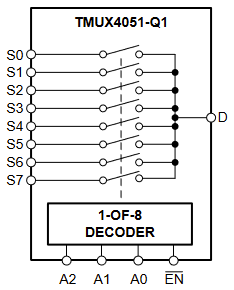
One possibility to save pins on the main card is to use an analog multiplexer.

enter image description here
Source: TMUX405x-Q1 Datasheet

But without additional info, it's hard to tell if this is a viable solution for your use-case.

\$\endgroup\$
2
  • \$\begingroup\$ I thought about MUX. It can help a bit but it is not the perfect solution. With it, I can free some pins but not so much. Still thank you for your help. \$\endgroup\$
    – MaxenceV
    Commented Apr 17, 2023 at 12:46
  • \$\begingroup\$ can you share some of the "from cpu" pins between multiple devices? that can make mux much more powerful - see S100 and ISA bus for examples. \$\endgroup\$ Commented Apr 18, 2023 at 12:56
6
\$\begingroup\$

It appears that you are very worried about radiation hardening and possible memory bit flipping, and do not care about any other sources of failure? Personally I have seen too many examples where someone has neglected the physical aspects of high reliability and fault tolerance and has run every signal in a single cable bundle or single bus, just waiting to be taken out by a single crush or fire event.

An analog solution would be to mix the analog signals up in frequency to a radio frequency signal, send all of the radio signals a single RF transmission line/coax, and recover the analog signal by down-mixing or a filter bank at the receiving end. Very simple and robust 1960's technology.

Another option may be a bank of optical LED and photo-transistors at different wavelengths. But I suspect that if memory flipping is a concern then the radiation sensitivity of the photo-transistors would be problematic.

\$\endgroup\$
6
\$\begingroup\$

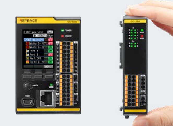
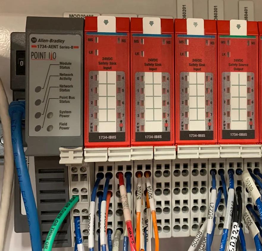
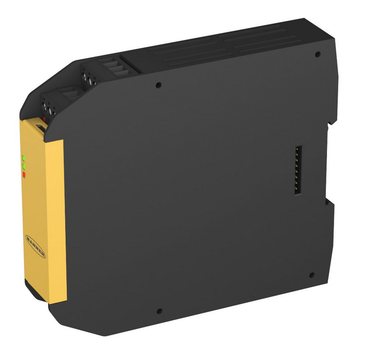
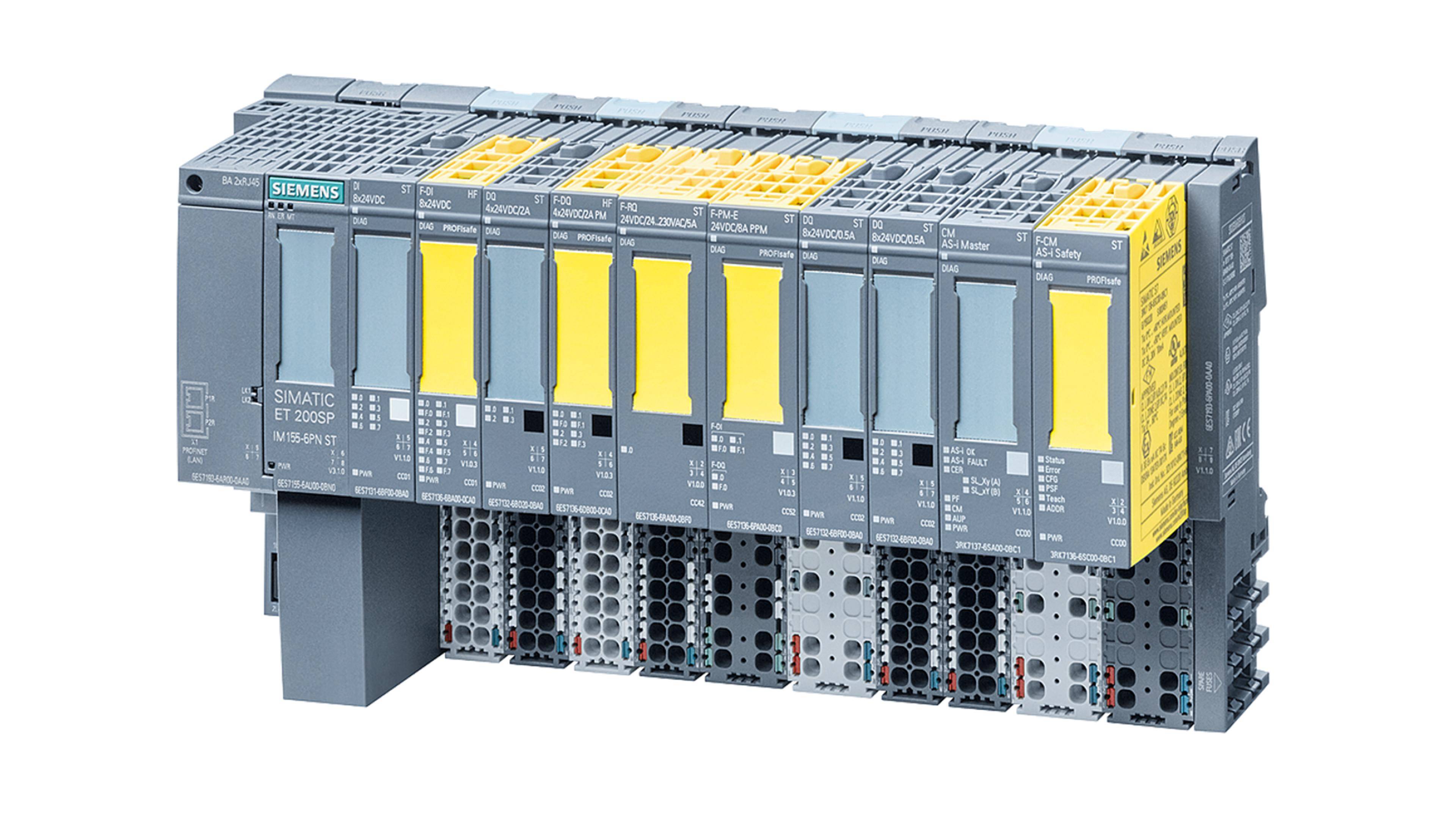
It looks very much like you're designing a safety PLC with an expansion-card bus, like a Beckhoff TwinSafe or Keynce GC1000 or Rockwell Guardlogix or Banner XS26 or Siemens ET200SP (Images at the end of the post).

Note the wiper/pogo/pluggable contacts on the side of all those modules. They all work on the same basic principle: Transmit sensor/logic power and ground, actuator/output power and ground, and a serial communication bus down the row of modules. It's no longer a typical design choice in the industry to plug dozens of cards into a single massively-connected PC / 104 backplane, or mandate that cards have no processor.

Instead, focus on making your communication protocol and receivers black-channel compliant. They must reliably transmit data even under the following circumstances:

  • Repetition
  • Loss
  • Addition
  • Incorrect sequence
  • Corruption
  • Delay
  • Incorrect addressing

Whether implemented by FSoE (Functional Safety over Ethercat) on EtherCAT, CIP Safety on Ethernet/IP, ProfiSafe on Profinet, or custom RS485/CAN/I2C or whatever, you typically solve this with two primary tools: CRC (cyclic redundancy check) error detection and watchdog timers. Depending on the bus layout, you may also need node addresses and sequence counters.

Instead of requiring that your system has no memory, prove that it will fail safe quickly if anything goes wrong. No memory does NOT guarantee that it's error-free, analog busses (yikes) or SERDES hacks are going to be prone to RF interference and hardware failure. Every contact on this backplane is a mechanical wear item, so you want to minimize the number of channels. In contrast, redundant processors and CRC math is cryptographically unlikely to err due to random noise. Microcontrollers are cheap, throw two on the board, compare their outputs with a filtered XOR, require them both to change the state of a watchdog flip-flopping at some minimum frequency on every packet, and if either measure says something's wrong, force the outputs to a safe state and seal that in until power-cycle (or save it in non-volatile memory until it's explicitly cleared!)

That's how the entire rest of the world is building these systems today: Backplanes are out, black channels are in.

See also:

Beckhoff 6910

Keyence GC1000

Rockwell GuardLogix PointIO

Banner XS26 Expansion Module

Siemens ProfiSAFE ET200SP

\$\endgroup\$
1
  • \$\begingroup\$ Thanks I will look into it. \$\endgroup\$
    – MaxenceV
    Commented Apr 20, 2023 at 7:05
5
\$\begingroup\$

I'm not sure if this meets whichever particular safety standard you're designing to, but here's how they solve similar types of issues in avionics and in many other types of safety-critical systems.

Your cards would use analog/digital converters that communicated over an I2C bus (or similar). To protect against the types of failures you're worried about, each signal is actually connected to three separate A/D chips, each a different design and from a different manufacturer. When taking a signal reading, all three are read and their results are compared.

This design doesn't prevent spurious errors like a cosmic ray hitting a memory cell and flipping a bit, but it enables you to detect these errors as an inconsistency between readings. A reading is only considered valid if the majority of the sensors agree. Inconsistent readings are thrown out and are not acted upon. The only way to encounter an undetected error is for some single anomaly to cause the exact same erroneus output on three completely independent implementations and at the exact same time, which is a feat considered essentially impossible for random, natural events.

I would build a system like yours with three I2C buses (or whatever protocol you're using). All your primary chips are on bus A, secondary chips on bus B, and tertiary chips on bus C. That way, you can read all the chips in a redundant set at the same time. That sort of arrangement would require six pins from your CPU (two for each bus), and you could add more cards and devices without requiring more pins. If you're completely pin-starved you could look into the 1-Wire bus but there aren't as many devices on the market that support that particular protocol.


If you're completely married to analog signals only, then the only improvement I see is to use single-ended signals. You give your signals names like IN+ and IN-, which implies you have a double-ended signal. You can get purely analog devices that convert double-ended signals to single-ended and vice versa. That would let all your inputs and outputs share a ground and you could go from 2 CPU pins per signal to 1.

\$\endgroup\$
1
  • \$\begingroup\$ Interesting idea. I think the company I am working for is already using this idea in other projects. Unfortunately, I cannot apply it to my case because I do not have time to modify all the designs of all the cards and the code of the CPU. \$\endgroup\$
    – MaxenceV
    Commented Apr 18, 2023 at 7:54
4
\$\begingroup\$

Make an analog bus:

  • Use up some lines on the backplane for address lines.
  • Use up fewer lines for analog signals
  • When a board "sees" it's address, it switches on its analog drivers and drives the analog signals; otherwise it stays high impedance.

This has obvious issues with bandwidth and signal integrity that you'll have to work out. At worst, you'll do that, and you'll realize (or have ammunition to make your higher-ups realize) that you do, indeed, need some robust little microcontroller on each board.

\$\endgroup\$
1
  • \$\begingroup\$ The idea is really interesting. I need to think more about it to see if it is doable in my system. Thank you. \$\endgroup\$
    – MaxenceV
    Commented Apr 18, 2023 at 7:50
3
\$\begingroup\$

Sure - you are looking for an ADC (analog-to-digital converter) with an interface like I2C, SPI, etc. that allows many devices to exist on one bus.

Of course, any of these bus protocols is more complicated than a simple analog signal. Make sure to read and understand it before making the hardware.

With I2C, the devices are simply wired in parallel. Each I2C device has an address, and usually you get to control 2-3 bits of the address by wiring 2-3 pins on the chip to Vcc or ground. That means a maximum of 4-8 devices on the same bus. The remaining bits might be different on different chip types so you could possibly have 8 of one chip and 8 of another and 8 of another. For more than that, you want an I2C multiplexer chip to direct the traffic to one of several busses.

An I2C bus typically runs at 400kHz, that is 400000 bits per second including the extra overhead bits (about 25%, so about 320000 useful data bits). If you have a lot of data to read or want to read it quickly, this might not be fast enough. Some devices support faster modes. I2C busses can't run faster than the slowest device.

With SPI, there is no problem of address conflicts, but it's more complicated than simple parallel wiring. To save wiring you want to try to use a daisy-chained arrangement which is supported by many but not all SPI devices. Otherwise, you can use a parallel arrangement, which requires a separate chip-select wire for each device, defeating the point, but you could use a demultiplexer chip to generate many chip-selects with a demultiplexer and a smaller number of CPU pins, since only one is active at a time.

There are also other protocols like CAN which I'm unfamiliar with.

\$\endgroup\$
8
  • \$\begingroup\$ After looking at the datasheet of an ADC with an I²C interface : (TLV320ADC3120), I am pretty sure that the data are going through a register (am I mistaken ?) which means that there is a possibility that my signature for the specific data can be remembered. Still thank you but as I said in my first post, I am pretty sure that it is not possible to do what I want :(. \$\endgroup\$
    – MaxenceV
    Commented Apr 17, 2023 at 15:10
  • 4
    \$\begingroup\$ @MaxenceV all serial protocols involve memory; so do almost all analog-to-digital converters \$\endgroup\$ Commented Apr 17, 2023 at 15:18
  • 4
    \$\begingroup\$ @MaxenceV If you get a chip that has a "reset" line on it, you can toggle the reset line each time before you use it to ensure that any internally-stored information gets forgotten. \$\endgroup\$
    – bta
    Commented Apr 17, 2023 at 21:00
  • \$\begingroup\$ That's not a bad idea but I have some doubts about the safety of this. I am quite new to all of this safety stuff so I might say something dumb so sorry for that if I do. If I use a reset signal, how can I be sure that the reset signal has been "understood" by the chip ? I thought about some ways to do it but none is really good. \$\endgroup\$
    – MaxenceV
    Commented Apr 18, 2023 at 7:49
  • 2
    \$\begingroup\$ @MaxenceV: Your sequence to verify reset occurred would look something like: (1) send the reset signal (2) read the configuration register (3) compare the value to the power-on default value (4) write the configuration register with the values you want (5) start data acquisition (6) wait for conversion complete (7) read the result data (8) read the configuration register again (9) compare the configuration to the value you wrote. That way step 3 proves that reset did occur at the beginning, and step 9 proves it did not occur partway through the data acquisition \$\endgroup\$
    – Ben Voigt
    Commented Apr 18, 2023 at 18:43
2
\$\begingroup\$

When you take the "cannot use anything that has memory" restriction literally, then using serial input is not an option. A serial input requires that the device knows the current state of the series, so it knows how the next signal is to be interpreted. Which requires the receiving device to have internal state. Which requires it to have some form of memory. Yes, a flip-flop circuit is technically one bit of memory.

However, when the writers of your requirements are only afraid of "digital" memory in form of integrated circuits containing semiconductors, then you could use analog memory. You could store the current state of the serial input using self-holding relays, for example. Welcome back to the 1940s.

\$\endgroup\$
2
\$\begingroup\$

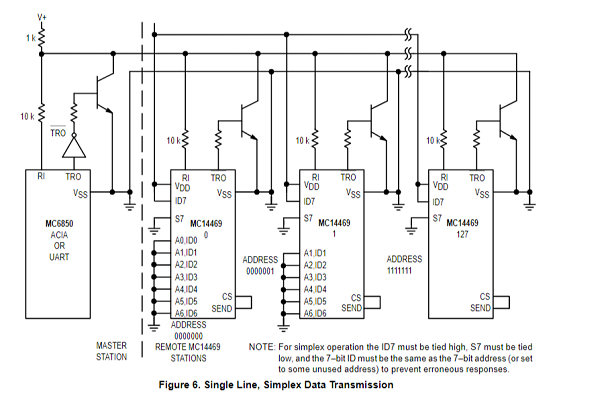
A long time ago in the 80s of last century I played with a serial communication IC that seems to fit exactly what you are describing: MC14469 from Motorola.
It implemented an asynchronous serial receiver/transmitter (UART) that does not require a CPU to be configured or to work.

(image taken from Motorola/Freescale datasheet

It can work on a 2- or 3-wire serial bus (TX outputs connected by wired-AND) that connects up to 128 "slave" nodes. It can be configured (by wiring) to be activated by a 7-bit address and answer with a 7-bit data word. Its max. data rate is 4800 baud (@5V) or 9600 baud (@12V).

\$\endgroup\$

Your Answer

By clicking “Post Your Answer”, you agree to our terms of service and acknowledge you have read our privacy policy.

Not the answer you're looking for? Browse other questions tagged or ask your own question.