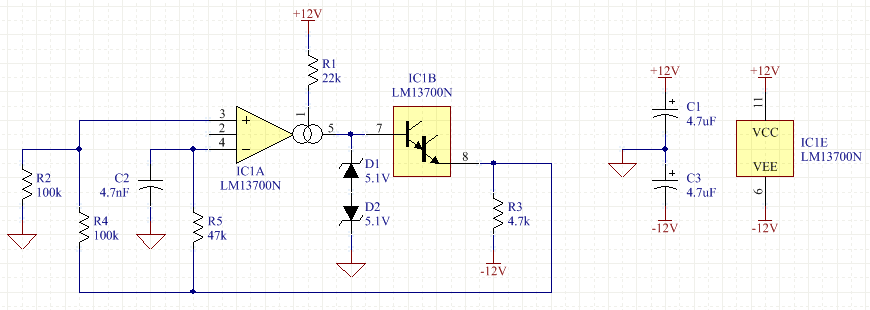
An example method is to use an op-amp with a current-limited or current-mode output. This uses the LM13700 transconductance operational amplifier (OTA) as a comparator with constant-current output:

(The zeners might be 1N5231B or similar.)
Internally, LM13700 is a differential pair into a chain of current mirrors, so its output (pin 5) is a current variable between ±Iabc (pin 1). The transfer function has a \$\tanh x\$ characteristic with respect to the input voltage difference, which is linear for small values but is an effective clipper here (i.e. the output current will be very close to ±Iabc).
(For inputs below 60mV or so, the proportional section of the \$\tanh x\$ curve becomes important, and this device can be used as an analog multiplier, variable oscillator or filter, etc. As such, it is a key element of pure analog synth instruments, and other kinds of analog computers.)
The output current simply flows into the zener diode stack, causing breakdown of one or the other, and thus the output is clamped at ±Vz.
The 'B' section is simply a Darlington emitter follower, provided as a crude voltage buffer. Here, a voltage output is required, so this is a convenient addition. (Note that it drops 2 VBE; you may need to adjust the diode clamping voltages for a given/desired output.)
Occasionally, one finds voltage-mode op-amps with the internal gain node (generally equivalent to pin 5 here) exposed to a pin, for purposes of external compensation or clamping. In that case, the same scheme can be used, or perhaps with steering diodes into fixed voltages to save on the capacitance of zeners. These types are mostly obsolete unfortunately, and the few that remain are highly specialized (e.g. moderately-high-speed video amplifiers with clamping for sync and level purposes).
Another example might be using a comparator proper (e.g. LM393), with a current-limiting resistor to its output pin, and a pull-up resistor, into a zener network much as here. The LM393 is an open-collector output, i.e. it can only sink current; therefore by choice of the pull-down and pull-up resistors, the positive and negative currents into the zener pair can be chosen. A voltage buffer may still be required.
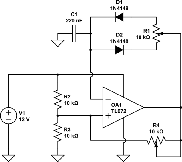
Note that hard-clamping the output voltage of a conventional voltage-mode op-amp need not have useful effect. That is, don't try the above circuit with a TL071 or etc.
For one, the output current is poorly limited (if at all), leading to at least high current consumption, if not destruction as well; for two, the internal gain node might saturate anyway, incurring recovery delay, plus whatever recovery delay the current limiting circuitry itself might add. Three, you always incur voltage slewing, requiring an extremely fast op-amp for some given edge rate, whereas the same circuit with a proper comparator might not require anything fancy at all.
For point of reference: even the slowest commonly available digital logic family, CD4000 at 5V, switches faster than TL071 at ±15V; and the contemporary comparator LM311 is significantly faster than both.
You might well ask why such a circuit [as yours] is a common illustration in circuit collections, prototyping kits, etc. Well, that's exactly it: it does the thing. It doesn't have to do it well. It just does it at all. Such a kit likely isn't going to supply a diversity of amplifier types, and doing so would probably confuse the user needlessly ("I need what this time?"). It's a demonstration of the possible, not a demonstration of sheer performance. Occasionally, poor performance is all that's required, and it's a perfect fit -- reusing a spare op-amp from somewhere else, for example.


