4
\$\begingroup\$

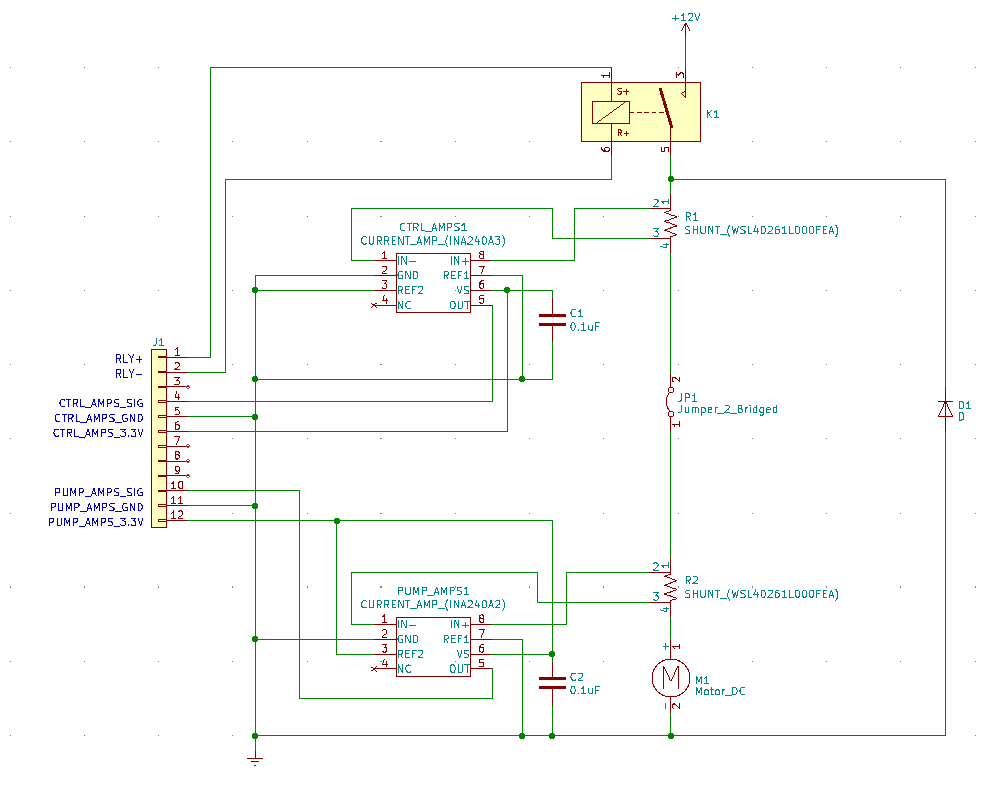
We have over 100 current shunt amplifiers (Texas Instruments INA240A2-Q1 and INA240A3-Q1) monitoring durability testing of brushed DC motors (more specifically, fuel pumps). On our test boards, there are two different configurations. In one case, we measure the current of a motor controller and the current of the pump it's controlling. In the other case, the current shunts are jumpered in series and both redundantly measure the current of just a DC pump (no controller). When in the pump-alone setup, the amplifiers routinely fail.

The amplifiers have a common-mode range of -4 to 80 VDC. Most of our testing is at 12VDC, and most pumps draw around 10-12A. Some run constant, and some are switched on and off with an automotive relay every few seconds. Tests run anywhere from 100 to 4,000 hours. Because of the automotive relay, a flyback diode was put in place to protect the the amplifiers. I've taken several scope traces when switching the relay on and off. The voltage never goes below -1 VDC. Sometimes there's ringing, and the voltage will go as high as 16 VDC. Anytime I measure, the voltage is always well within the amplifier's range.

You would assume that the on/off testing would be the most abusive and cause most of the amplifier failures, but the steady-state testing will cause just as many failures. Sometimes a test will run for hundreds of hours before failure, while other times the amplifier will fail after a few minutes. When there's a controller/pump test, we haven't seen any failures (on either amplifier). The failures only happen when both shunts are in series, measuring the pump-alone current. More often than not, it is the "Pump" amplifier that fails. The "Controller" amplifier does fail, but much less often.

I'm scratching my head. It's such a simple circuit, and the voltage is within the amplifiers range. Here's the circuit. J1 interfaces with the rest of the test control circuits and not shown for simplicity. The 3.3 VDC powering the amplifiers is a high quality source, and I've checked it many times.

The current shunts are 0.001 ohm, 3W.

enter image description here

\$\endgroup\$
18
  • \$\begingroup\$ How do they fail? Short on Vcc? Unreliable readings? ”Sometimes there's ringing, and the voltage will go as high as 16 VDC” What’s your Vcc in this condition? \$\endgroup\$
    – winny
    Commented Apr 22, 2023 at 16:06
  • \$\begingroup\$ Have you checked that the flyback diode is still working? \$\endgroup\$ Commented Apr 22, 2023 at 16:20
  • \$\begingroup\$ @winny The failure mode is that OUT sticks at 3.3 V indefinitely. Power supply voltage to the motor is 12 V. It is always at 12 V expect occasionally spiking to 16 V when the relay switches. \$\endgroup\$
    – gtetil
    Commented Apr 22, 2023 at 16:31
  • \$\begingroup\$ @AndrewMorton Yes, all of the flyback diodes are still working. When the relay switches off, the negative voltage is always clamped to around -1 V. \$\endgroup\$
    – gtetil
    Commented Apr 22, 2023 at 16:33
  • 2
    \$\begingroup\$ This is almost certainly EOS from a fast transient that you haven't been able to catch on the scope yet. It could be over/undershoot due to parasitic inductance and capacitance in the diode/motor loop. I know you probed and only saw -1 V, but look for very fast transients maybe by setting the trigger to -2V and seeing if you get a sweep. You should measure right from the ground pin of the INA240 to the - input of the device. These parts are reliable when used within the common-mode range and other abs max specs, so there is something you're missing. \$\endgroup\$
    – John D
    Commented Apr 22, 2023 at 18:24

5 Answers 5

2
\$\begingroup\$

You run the motors from +12V. Probably D1 is why there is no more than -1V across the motor. It may be that the loop of M1 R2 R1 D1 is large and D1 is not clamping the voltage well. You could place the diode across the motor.

It is common to place a diode across the relay coil. It will "fly back" a large voltage when it is deenergized.

\$\endgroup\$
5
  • \$\begingroup\$ The diode is working well. It always clamps the voltage to -1 V anytime the relay opens. I can measure anywhere in the circuit before or after either of the shunts. It never goes below -1 V. I also tried a diode across the motor as close as possible. The scope traces are the same, and the failures remain. \$\endgroup\$
    – gtetil
    Commented Apr 22, 2023 at 16:36
  • \$\begingroup\$ @gtetil I think that ronsimpson was referring to adding a flyback diode across the relay coil in addition to the flyback diode across the motor. \$\endgroup\$ Commented Apr 22, 2023 at 16:43
  • \$\begingroup\$ @AndrewMorton Thank you, I missed that. A diode on the relay coil would just provide protection from what's driving the coil, right? It's not in the diagram I provided, but the relay is driven by a MOSFET with an integrated diode. \$\endgroup\$
    – gtetil
    Commented Apr 22, 2023 at 16:49
  • \$\begingroup\$ @gtetil For the price of a 5 cent (Schottky) diode, is it worth giving it a go? I realise it may take a few hundred hours of testing, but it's the sort of thing that should be in place as a matter of course, from what I understand. And close to the inductive element to minimise the current loop. I am not an EE professional. \$\endgroup\$ Commented Apr 22, 2023 at 16:55
  • 1
    \$\begingroup\$ @AndrewMorton The relay I'm using has an integrated diode: digikey.com/en/products/detail/… \$\endgroup\$
    – gtetil
    Commented Apr 22, 2023 at 17:00
2
\$\begingroup\$

Ideally the voltage will swing up to about 24V when the relay coil opens, due to ringing with the coil self-capacitance and clamping by D1.

But if there's a bit of inductance in the supply line due to bad layout etc. (maybe the wires are not twisted and it looks like there's no bypass capacitor on the 12V) you can get considerably more, maybe enough to exceed the 80V absolute maximum.

This particular part can't tolerate much in the way of series resistance on the inputs, but maybe you could add add one or more TVS diodes to ensure there's no spikes.

\$\endgroup\$
2
\$\begingroup\$

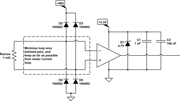
Assuming you're not doing anything funky at the amplifier outputs or supply rails (we don't see anything on the other side of J1), then it's likely that there's some very fast and large transients that you are not picking up on the scope, and if you are unable to find them, maybe the best option is to lay down the law yourself, with clamping everywhere. Also, take care with signal routing:

schematic

simulate this circuit – Schematic created using CircuitLab

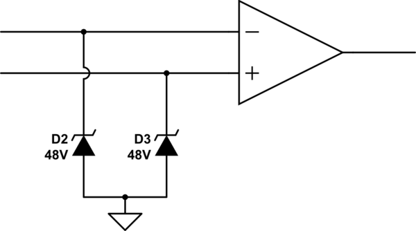
I used regular diodes D2 and D3, clamping against a high voltage source because of their low reverse leakage current. You could use zener diodes or a TVS (shown below) if their reverse (leakage) current is well below 1μA. More leakage than that will affect measurement accuracy since it's significant compared to the amplifier's input bias current of 90μA.

My choice of 48V is arbitrary, but it needs to be less than the amplifier's maximum input voltage of 80V, and greater than (or equal to) the motor's own power supply voltage. You could use the motor's own power supply, but if that's where the transients are, then it defeats this protection. It's better to find an independent clean and low impedance source to clamp against.

For this reason, and others, clamping against ground has its advantages, and if you can find a TVS with low enough leakage current, then this would probably be the better option:

schematic

simulate this circuit

Also, install a diode directly across the relay coil, and very close to it. That way you protect everything, and keep flyback current loop area small.

\$\endgroup\$
3
  • \$\begingroup\$ I had considered TVS's before, but it is difficult to try in my setup without a complete board re-design. I will circle back to this and see if I can figure out how to hack these in, at least for debug, then think about a new design. \$\endgroup\$
    – gtetil
    Commented Apr 23, 2023 at 13:14
  • \$\begingroup\$ I have little to no experience specifying a TVS. I selected one based on some rudimentary knowledge. Do you think this one is right for the job? I chose one with a Vr of 30V because we occasionally will test a 24V pump. digikey.com/en/products/detail/littelfuse-inc/SMAJ30A/762294 \$\endgroup\$
    – gtetil
    Commented Apr 23, 2023 at 14:04
  • \$\begingroup\$ @gtetil That's exactly what I would try, yes. \$\endgroup\$ Commented Apr 23, 2023 at 22:59
1
\$\begingroup\$

If there are no problems when testing BLDC motors, only brushed DC motors, that suggests noise from the brushed motor, which is not unreasonable. Also, you mentioned that you get failures when testing the motors in steady-state operation, so this eliminates the relay, in this scenario. With this information, I would work to filter the noise at the PCB-motor connection. Use the methods already mentioned (diode, TVS, etc.), but I would add filtering like capacitors or RC snubbers. I think it would be useful to look at the noise at the PCB-motor connection with a scope: use AC coupling and adjust the sensitivity to see the noise and then add the selected components to reduce it.

Also, double check the 12V return current path and make sure there's no chance for the motor current to want to flow to the 3.3V grounds. And, as has been mentioned, look at the area of this current loop -- +12V supply, shunts, motor, return to 12V ground -- and work to minimize it, if you can, and check to see that it can't induce a voltage in the other circuitry.

One other thing to try is putting a common-mode choke on the path to the motor to help suppress any high-frequency noise that might be an issue. You could also accomplish this off-board by passing both of the motor's wires through a ferrite toroid ("doughnut") or use a clamp-on ferrite.

Best of luck on Monday!

\$\endgroup\$
1
  • \$\begingroup\$ All excellent suggestions. I will work on these tomorrow. As the conversation has progressed, I too am convinced it's a transient. I just haven't ever caught anything on the scope yet. But, it sounds like maybe I'm not looking in the right place, or my setup is wrong. Yes, it only happens on controller-less brushed pumps. Some pumps have built-in RFI's and others do not. This could be part of the variability in failures. Also, perhaps the brush/com is wearing a certain way over time causing failures at random hours of testing. \$\endgroup\$
    – gtetil
    Commented Apr 23, 2023 at 16:26
1
\$\begingroup\$

I've had many strange debug experiences over the years, but this one takes the cake. Took 2 days to find the issue, but I believe this one is solved. I could write 10 pages on how we came to find the issue, but to keep this concise, we'll go straight to the problem.

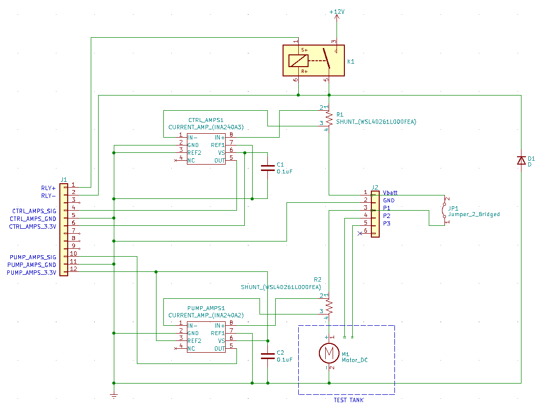
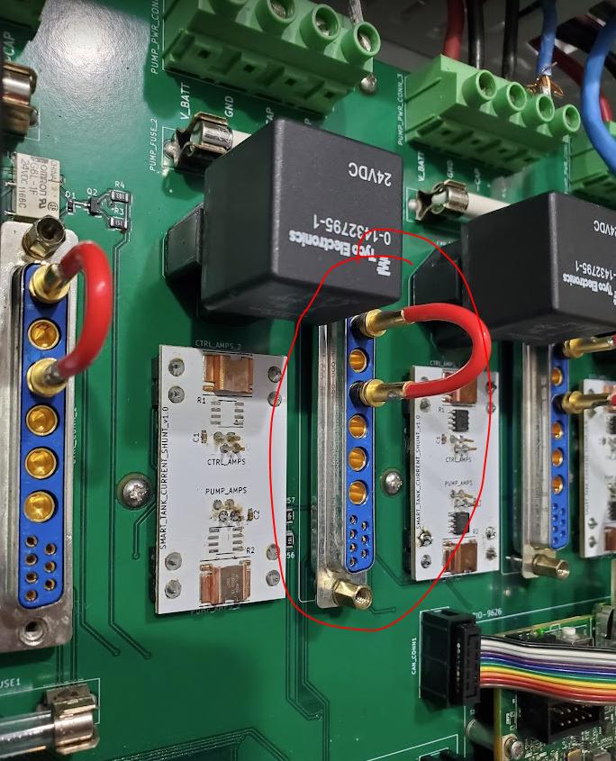
First, let me add a little more detail to the circuit. Some might say I should have given the detail up front, but I seriously doubt anyone would have put this together. J2 is the connector interface where we can jumper and run a brushed pump alone. We can also connect a wiring harness to J2, and run it to a BLDC controller. In BLDC mode, Vbatt and GND go to the controller, and the phase wires (P1-3) go from the controller to the pump. In brushed mode, Vbatt gets jumpered to P1 to send power straight to the pump. P2 and P3 just hang out.

enter image description here

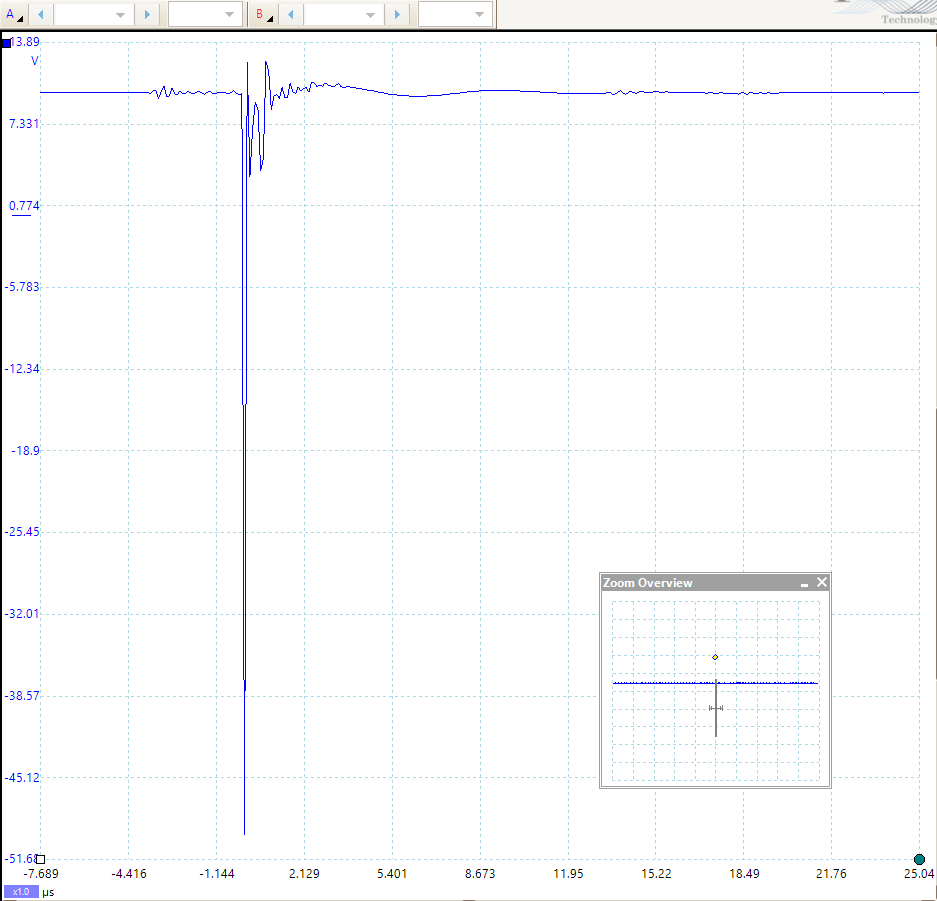
As suggested, we set the scope at a very high sample rate and set a trigger. There are six pumps per system. We chose the pump that has caused most of the documented failures. The test calls for a constant run (no on/off cycles). Within a few minutes, we caught a transient!

enter image description here

I think we can all agree this can kill the amplifiers. Standing there with the electrical cabinet open, we noticed there was an arcing sound when the transient was caught. We set up the trigger again. Transient caught, and an arcing sound. You could set your watch to it. Over and over again. Every 8 minutes a transient and arc occurred.

We located the arcing (after several hours of painstaking debug). It was happening between P1 and P2. What!?!?! P1 is powering the pump via the Vbatt jumper, and P2 isn't doing anything in this setup. P2 is open on both ends!

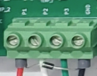
Here's a pic of the J2 connector showing the jumper and the open connections. The leads go through several layers of large copper traces to handle the load, then exit the bottom of the board through another connector.

enter image description here

A wiring harness interfaces with this connector, and out to the pump in the test tank.

enter image description here

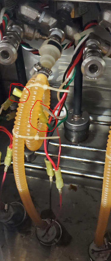
Here's a pick of the test tank showing P2 and P3 with no connections (green and white wires).

enter image description here

A pic of the wiring harnesses behind the tank. Ugly, I know.

enter image description here

While running, the active P1 wire (red) was coupling with the unconnected P2 and P3 wires (white and green). A charge was being built up on these wires like a coil. Every 8 minutes, the white wire had enough and dissipated from P2 to P1 on the J2 connector. In practice, you usually think right away that an arc jumps to ground. But P2 must have been at a high enough potential difference from the Vbatt-level P1 pin.

All 6 pumps in the system share the same power supply. The negative spike was able to navigate through Vbatt and knock out all of the other amplifiers. I'm going to assume that the other pumps cause the same transient too, but likely at a different frequency that we haven't noticed yet, and perhaps a faint enough arc not to notice.

The fix. From here on out, on all brushed pump testing, jumpers will be installed to take P2 and P3 to GND. We may also consider installing TVS diodes to protect the amplifiers from any future unknown transients.

Is it the DC current causing the coupling, or the AC ripple from the motor commutations on top of the DC? Or both? Also, does the twisting of the wiring harness increase or decrease the coupling?

Thank you everyone for all of your help on this one!

\$\endgroup\$
7
  • 1
    \$\begingroup\$ Thanks for the update. It still does not make a lot of sense to me, coupling does not generally cause charge to build up. I wonder if you’ve somehow inadvertently created a Van de Graaf generator via the pumps (is the liquid dielectric?) or there is some triboelectric effect from friction somewhere. Seems like the sort of thing that could cause explosions in a less benign environment. \$\endgroup\$ Commented Apr 26, 2023 at 16:16
  • \$\begingroup\$ I actually ran into a similar situation a few years ago (can't talk about specifics too much) but intermittent sparking was causing brief disruption to data communications. \$\endgroup\$ Commented Apr 26, 2023 at 16:26
  • \$\begingroup\$ @SpehroPefhany Most fuels actually have a level of conductivity. The two open wires are not in contact with the fuel though. \$\endgroup\$
    – gtetil
    Commented Apr 26, 2023 at 16:32
  • \$\begingroup\$ Wow, that's definitely one for the record books! And nice sleuthing! \$\endgroup\$ Commented Apr 26, 2023 at 18:48
  • 1
    \$\begingroup\$ I definitely think Spehro Pefhany is spot on about an ESD issue. To get repeated arcing that you can hear requires a source for the high voltage. Maybe the pump? I also notice in one of the pictures that the white wire looks to be touching the orange flex house. Maybe this could be the source. \$\endgroup\$ Commented Apr 26, 2023 at 19:00

Your Answer

By clicking “Post Your Answer”, you agree to our terms of service and acknowledge you have read our privacy policy.

Not the answer you're looking for? Browse other questions tagged or ask your own question.