1
\$\begingroup\$

I have three 12V indicator LEDs which are the simplest way to see if one of the three circuits is 'ON'.

Only ONE of the LEDs can be ON at any given time. They all share GND and a controller sends POS to each, as it's activated.

I need to sink a GPIO pin on an ESP32S3 to GND when any one of the three LEDs are ON.

My thought was to use a 12V relay, with the OUTPUT connected to the GPIO pin and GND, so when the relay is energized it would sink that GPIO pin to GND.

On the relay input side my thought was to use the GND from the three LEDs, which is a common ground for the relay negative, and then connect each of the LEDs' positive through a diode, to the relay positive.

Anytime an LED was lit, it would energize the 12V relay connecting the output pins and effectively sinking the GPIO pin to GND.

Does anyone see any issues with this?

Will the diodes be sufficient to keep the other LEDs from being lit when one is ON?

Is there a better way to do this?

I also have access to a single 120V circuit and a 120V solenoid, that are live when any one of the lights are ON. I tried using a magnetic reed switch to sense the energizing of the solenoid but the reed was too sensitive or something and fluctuates rapidly on/off when the solenoid is activated. I was trying to stay as non-invasive as possible.

UPDATED - SCHEMATIC ADDED
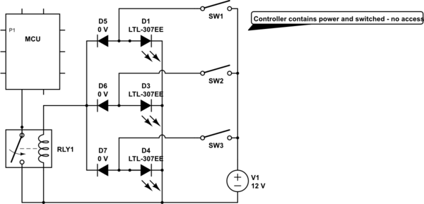
schematic

simulate this circuit – Schematic created using CircuitLab

\$\endgroup\$
4
  • 2
    \$\begingroup\$ Scematic diagrams are an excellent way to geta response here. I suggest using the schematic editor built in the the question editor \$\endgroup\$
    – user319836
    Commented Apr 25, 2023 at 3:04
  • 2
    \$\begingroup\$ Please add to your question: Do the 12V indicator LEDs share one terminal? Does the microcontroller need to be isolated from this potential? (A schematic diagram may or may not give the first piece of information.) \$\endgroup\$
    – greybeard
    Commented Apr 25, 2023 at 5:08
  • 2
    \$\begingroup\$ A diagram or circuit would be useful, you can do it on paper and upload it, with a program or with the website "circuitlab.com". A graphic helps other people to understand your problem much faster. \$\endgroup\$
    – MikroPower
    Commented Apr 25, 2023 at 7:25
  • \$\begingroup\$ I've added a schematic of what's in my head, dangerous I know.. will something like this work well? \$\endgroup\$
    – revive
    Commented Apr 25, 2023 at 17:31

4 Answers 4

1
\$\begingroup\$

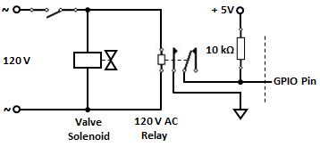
A single 120 V AC relay, with gold-plated contacts, should do.

Here's the schematic.

enter image description here

\$\endgroup\$
5
  • \$\begingroup\$ I presume you are referring to the alternative 120v circuit that is available, though less accessible. That is definitely an option. ** Why is the 10k ohm resistor needed between 5V+ and the GPIO Pin? \$\endgroup\$
    – revive
    Commented Apr 25, 2023 at 17:34
  • \$\begingroup\$ what is the 10k resistor needed for as I will only need to sink the GPIO pin to GND, not 5V? \$\endgroup\$
    – revive
    Commented Apr 25, 2023 at 19:32
  • \$\begingroup\$ @revive. Without the resistor, your GPIO pin would be floating (undefined). \$\endgroup\$
    – Marla
    Commented Apr 25, 2023 at 20:02
  • \$\begingroup\$ @vu2nan I have that GPIO pin set to INPUT_PULLUP which engages an internal resistor on that GPIO.. so, I presume the 10k can be omitted? \$\endgroup\$
    – revive
    Commented Apr 25, 2023 at 20:13
  • \$\begingroup\$ @revive - Yes, in that case the external pull-up is not required. \$\endgroup\$
    – vu2nan
    Commented Apr 26, 2023 at 2:47
3
\$\begingroup\$

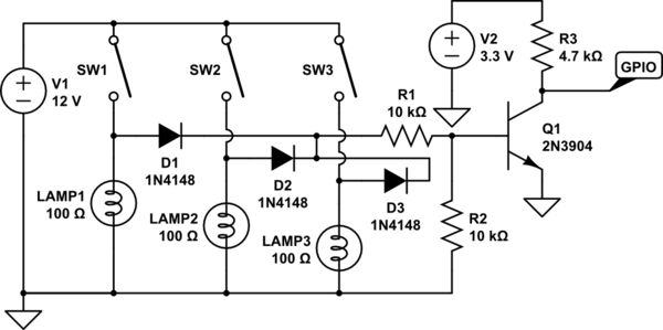
The simplest way to do this probably is as follows:

schematic

simulate this circuit – Schematic created using CircuitLab
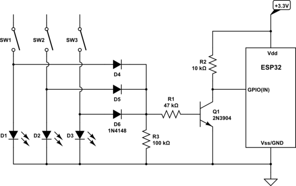
Assuming the lamps are individually driven by 12V, any one that is lit will turn on Q1, which will give a logic low signal to the ESP32. I show incandescent lamps, but LEDs will work the same.

\$\endgroup\$
0
2
\$\begingroup\$

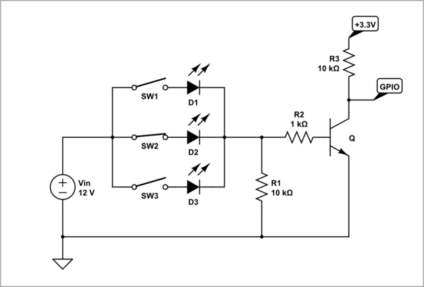
You need NOR logic gate which can be really made with diodes. LEDs are also diodes but "light emitting diodes"; so we can made them perform both logic and visualizing functions. Therefore, the PStechPaul's circuit can be simplified.

schematic

simulate this circuit – Schematic created using CircuitLab
Usually, the GPIO has an internal "pull-up" resistor that should be enabled in this case; so R3 can be omitted. R1 can be also omitted but it is better to have it.

I tried using a magnetic reed switch to sense the energizing of the solenoid but the reed was too sensitive or something and fluctuates rapidly on/off when the solenoid is activated.

A reed switch or a reed relay? I can help you to realize this idea...

\$\endgroup\$
2
  • \$\begingroup\$ Re: your diagram, is it possible to replace Q with a 12v relay? I don't see how each of the LEDs will not turn the others on, without a diode in front of it.. \$\endgroup\$
    – revive
    Commented Apr 27, 2023 at 23:55
  • \$\begingroup\$ In principle, it is possible (with a 9 V relay up to 30 mA, for example) but it is not a good solution and, above all, it is not necessary. The other LEDs cannot light up because there are open switches in series to them. \$\endgroup\$ Commented Apr 28, 2023 at 5:27
1
\$\begingroup\$

I think your circuit looks good, the diodes are a nice touch. You did forget the obligatory diode across the relay coil to keep it from killing everything when it switches off.

Instead of powering a relay coil, though, a quieter, less power hungry solution would use a transistor:

schematic

simulate this circuit – Schematic created using CircuitLab
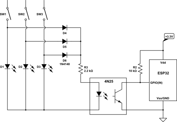
This assumes you are able to join the grounds of the two systems together. If not, or if you are unsure, then isolate the two systems using an opto-isolator, such as the 4N25:

schematic

simulate this circuit

\$\endgroup\$

Your Answer

By clicking “Post Your Answer”, you agree to our terms of service and acknowledge you have read our privacy policy.

Not the answer you're looking for? Browse other questions tagged or ask your own question.