10
\$\begingroup\$

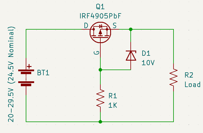
I'm using this circuit for reverse polarity protection.

The load draws 20A (11 DC motors) continuously for 2 hours after which the battery gets replaced. Even with a heat sink, the MOSFET gets extremely hot. Whenever there is a battery swap, I intentionally connect the battery in reverse to see if the behavior is as intended.

Some of these MOSFETs have been running for days while others started conducting in reverse just 10 minutes into testing and I'm absolutely clueless as to why this is happening.

Is it just a bad batch of MOSFETs?

How to make it run less hot without a fan? A better MOSFET?

Here is the datasheet of the MOSFET.

Reverse Polarity Protection

\$\endgroup\$
1
  • \$\begingroup\$ Use a better part - BUT: For interest: lcsc.com/products are a reputable Chinese reseller. They offer money back on fakes (as you'd hope) and obiously try hard to sell genuine parts. || They list two suppliers of the part listed here - from Infineon and VBsemi \$\endgroup\$
    – Russell McMahon
    Commented May 10, 2023 at 13:19

4 Answers 4

9
\$\begingroup\$

For 20A continuous I would suggest using a better MOSFET. That one has 20mΩ maximum Rds(on) at room temperature and 10V drive, which means more like 30mΩ when hot. That means at 20A you could have 12W of dissipation, which is a lot. Motors also have a surge current which can damage MOSFETs, which could be a secondary issue. A 4.5mΩ part would likely dissipate more like 2W, which does not require much of a heat sink. If you put two in parallel you might not need a heat sink at all (the second MOSFET might also be cheaper than the heat sink).

If you could use an N-channel and put the protection in the ground line it would be better again (because 1mΩ N-channel MOSFETs are easily available), but that's often not possible.

\$\endgroup\$
1
  • \$\begingroup\$ The current rating on a MOSFET is generally much higher than it can practically carry continuously. A MOSFET running near its current rating gets very hot. \$\endgroup\$
    – John Doty
    Commented May 10, 2023 at 13:04
8
\$\begingroup\$

There are chips called "Diode Controller" or "Ideal Diode" that allow you to use an N-channel MOSFET instead of a P-channel MOSFET. As mentioned in another answer, N-channel MOSFETs are available with significantly less Rds(on) resistance compared to P-channel MOSFETs.

\$\endgroup\$
3
\$\begingroup\$

As to why some of the MOSFETs short circuit, it could be

  • Excessive temperature during operation ("extremely hot" says the question). As pointed in that other answer, dissipation is bound to be high.
  • Negative ESD on the drain.

If only minor modifications are possible, I'd

  • Put a 100nF capacitor from drain to negative to mitigate the ESD risk.
  • Increase the zener voltage to like 15V to 18V: VGS can safely be up to 20V, and that can only help reduce power dissipation.
  • Put a heat sink with proper mounting (flat surface, tight screw, heat-conductive paste).
  • MOSFET with lower advertised on resistance, e.g. SUP70101EL or SUP90P06-09L

For a more complete redesign, I'd definitely use an N-channel MOSFET, which can have better on characteristic for the same price/package.

  • A simple option is the same circuitry (except for MOSFET kind and diode polarity) inserted on the negative. That should be adequate if negative is floating (things get complicated if negative is connected to some conductive chassis).
  • If the protection must be on the positive side: this seems a good indication for a diode controller; perhaps LTC4359.

Or, perhaps better: remove the need for reverse polarity protection (and associated losses) by a better choice of connector/cabling?

\$\endgroup\$
3
\$\begingroup\$

One thing you need to be well aware of is that if you bought those IRF4905 MOSFETS from an eBay (e.g. China/Shenzen) vendor they are extremely likely to be fake.

I nearly set fire to some equipment using eBay fakes - it was only when I blew the top off one of the device, I found a 1mm x 1mm die rather than the expected 5mm x 5mm die. Its easy to check - turn the device on, measure the voltage drop - it should be millivolts at 1 or 2 amps and it turns out to be more like one volt...

Even when running with a fraction of the rated 70 amps for this device type they were melting solder and charring the PCB.

Unfortunately, trying to prevent this issue by buying more expensive parts from China does not work. I bought three different batches before giving up: The devices are accurately marked as IRF but the fraudsters have spent all the money on the printing of the markings, not the silicon inside !

Go to Mouser.com or element14.com or whatever, pay about £2 or $2 per device and get the genuine part. Then try again.

\$\endgroup\$
1
  • \$\begingroup\$ For interest: lcsc.com/products are a reputable Chinese reseller. They offer money back on fakes (as you'd hope) and obiously try hard to sell genuine parts. || They list two suppliers of the part listed here - from Infineon and VBsemi \$\endgroup\$
    – Russell McMahon
    Commented May 10, 2023 at 13:18

Your Answer

By clicking “Post Your Answer”, you agree to our terms of service and acknowledge you have read our privacy policy.

Not the answer you're looking for? Browse other questions tagged or ask your own question.