0
\$\begingroup\$

I am trying to design a transformer that can be used for field testing of MCBs up to 32 A (Type C). The testing (for short circuit tripping of The MCB) will require maximum about 350 A to be injected into the MCB for about a 1 second. For testing Suitable cables and the MCB to be tested will be connected to the secondary of the transformer. Therefore the transformer will be always be used with its secondary short circuited. The weight of the transformer is critical since the kit should be portable to be carried around for field testing. Preferable weight 8-10 kg, but max 15 kg. The supply voltage is 230 V (+/- 5 %). There are many design challenges and options, but my most important question is - Will a toroidal core transformer be a better choice for the application?

Details -

There will be at least 5 min gap between tests. Each test lasting less than 100 ms. The test current may not be 320A every time. It will depend on the current rating of the MCB to be tested. Yes there is a protective circuit to shutdown the test within 150-200 ms. Therefore I may be not running into temp rise of the winding - that can increase the resistance and reduce the test current. But I will check that as you advice.

Two pieces of 3 meter long, 25 SQMM copper cables will be used to connect the MCB under test. Therefore the the total resistance will be about 30 mili ohms. Thus the required open circuit voltage will be close to 9.7 volts and the VA requirement will be about 10 X 320 = 3200. Thus the two cables and the transformer are making the setup little heavy to carry around. Looks like it is physically impossible to reduce the weight of the kit down to 12- 13 kg by any other method.

But one question bothers me. What increases the regulation of these kind of transformers ? Can the regulation be brought down to 20-25% at 10X current rating?

\$\endgroup\$
5
  • 3
    \$\begingroup\$ Why transformer? Get a portable engine start booster. Should be able to provide a few 100 A at ~12 V. \$\endgroup\$
    – tobalt
    Commented May 12, 2023 at 6:37
  • \$\begingroup\$ How accurately do you need to control the current? For a portable device, think of the required device as a low voltage, high current AC generator, not a transformer. Portable "kW inverters" don't use mains frequency transformers any more. Then again, if you can control on- and off-time with some precision, you can massively overload an iron core transformer compared to continuous rating. \$\endgroup\$
    – greybeard
    Commented May 12, 2023 at 7:14
  • \$\begingroup\$ (A toroidal core transformer should be lighter than a UI or EI one. I remember a tighter coupling, doing no wonders to limit current. Cut tape cores are somewhere in between, allowing to introduce a (split) air gap. Winding is easier.) \$\endgroup\$
    – greybeard
    Commented May 12, 2023 at 7:40
  • 1
    \$\begingroup\$ An arc welding transformer could help there. \$\endgroup\$
    – Jens
    Commented May 12, 2023 at 12:15
  • \$\begingroup\$ @tobalt Primary injection testing for breakers is often AC \$\endgroup\$
    – Jeroen3
    Commented May 15, 2023 at 9:44

3 Answers 3

5
\$\begingroup\$

I spent most of my career designing, building, and servicing circuit breaker test sets, ranging from small lunch-box sized units capable of 100 A continuous, to large desk-sized units capable of 4000 A continuous. And all of these were able to supply up to ten times their nominal current rating for short times of 100 mSec, which is used for instantaneous trips.

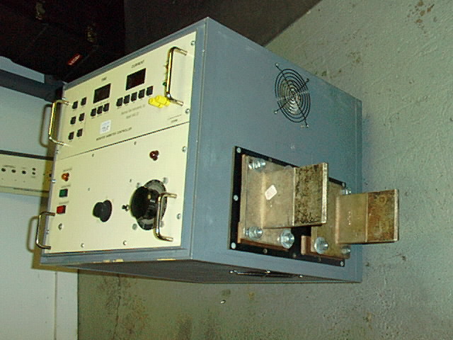
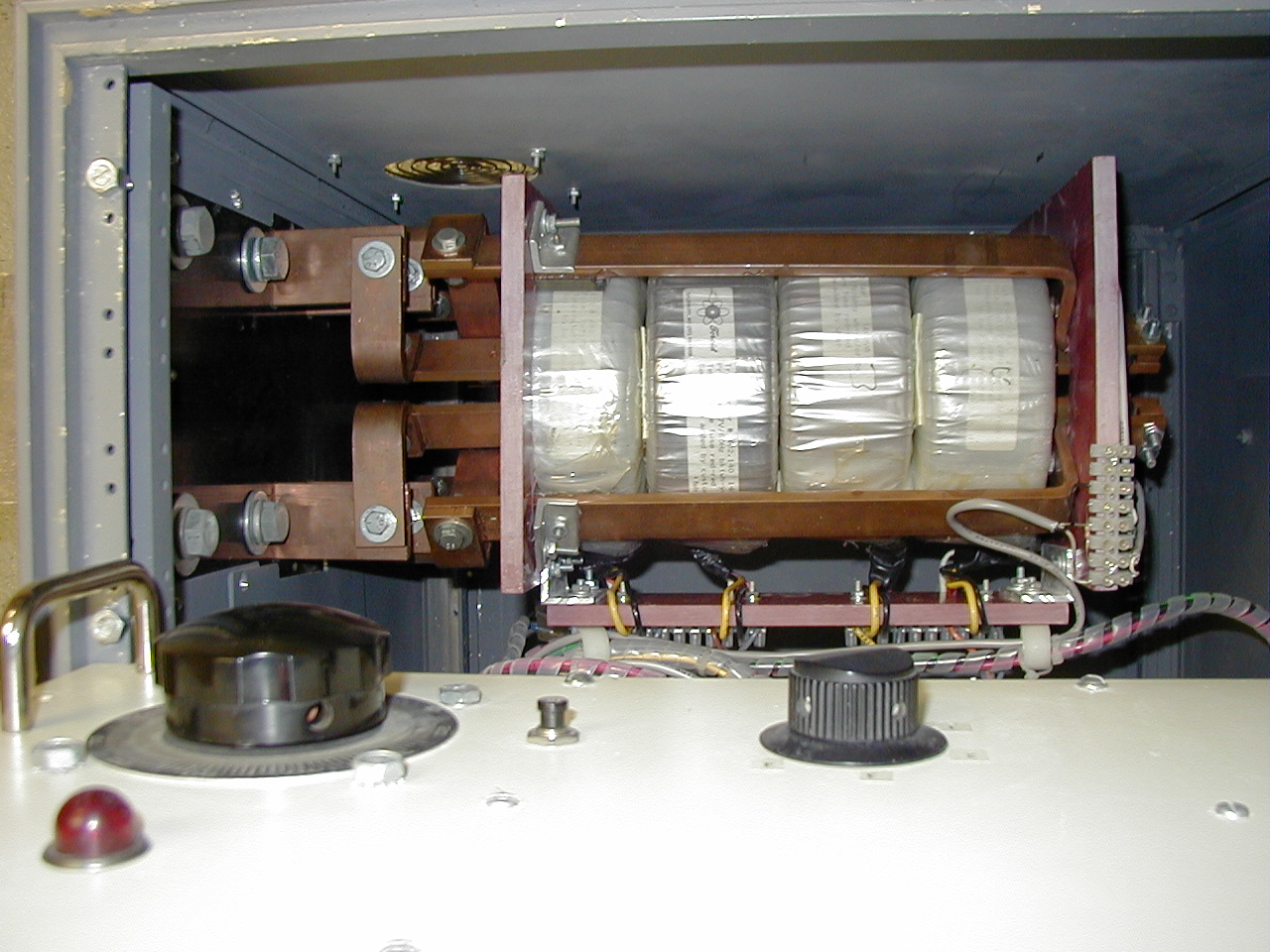
Here is a medium-sized test set built using four 1.4 kVA toroidal cores with 1/4" x 1" copper bus bar secondaries, which can be connected in series, parallel, or s/p, for 2.8 V @ 2000 A, 5.6 V @ 1000 A, and 11.2 V @ 500 A. It was capable of 10,000 A into a short.

PI-1000x

PI-1000x

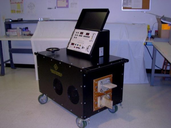
Here is one of the largest circuit breaker test sets, capable of almost 100,000 amps into a short, and 40,000 amps into a 4000 A breaker:

PI-6000

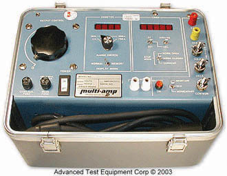
And one of the smallest units, capable of about 200 A continuous and 1000 A into a short:

Multi-Amp MS-2

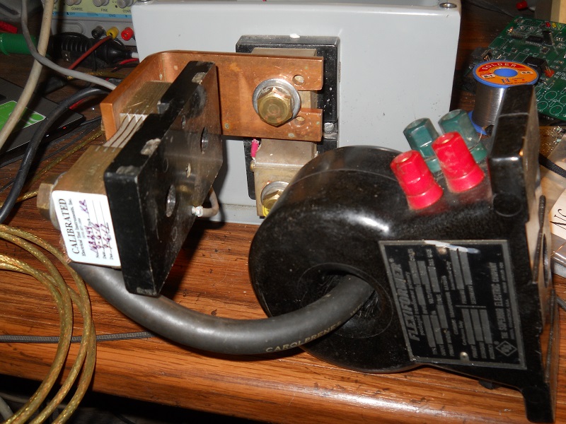
Here is a test set-up that I use for calibrating my ORTM-4H test devices. It consists of a 150 VA toroid having 400 turns of #24 AWG and 0.3 volts/turn at nominal 120 VAC. I typically get at least 700 amps into two 1000A/100mV shunts as shown:

Ortmaster testing

For circuit breaker testing, you need to supply a current pulse with minimal DC offset distortion, which requires a dual SCR controller capable of adjustable initial firing angle of 60 to 90 degrees. The measurement system needs to be able to analyze the current waveform to compute the true-RMS value for pulses as short as 1/2 cycle. The instrumentation I designed uses a Rogowski coil and integrator circuit, with ranges from 100 A to 10,000 A for smaller test sets, and 1000 A to 100,000 A for larger units.

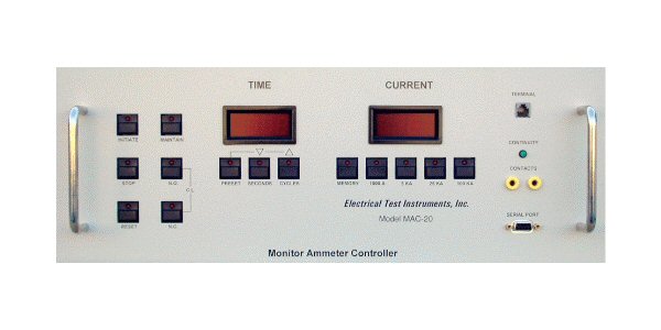
Here is the MAC-20, which performs monitor and control of test currents:

MAC-20

For more information, see my website www.pstech-inc.com.

A short article, "Taming the Big Bang", provides a light-hearted introduction to circuit breaker testing and tells how the Z-World SmartCore helped with the design of the BTSMASTER.

An older article, Circuit Breaker Testing Technology, originally appeared in Electrical Manufacturing magazine, in 1989.

(edit May 15) A 1.4 kVA toroid transformer "kit", consisting of just a factory wound 117 VAC primary, is available for about $150 from https://toroid.com/product/transformer-kit-1400va-402-140/. It weighs probably no more than about 5 kg, and it has 0.72 V/turn, so ten turns would give you 7.2 V at 200 A continuous, and up to 2000 A (10x) for 500 ms. You would also need a similarly rated "Variac", which will have about the same weight.

\$\endgroup\$
2
  • \$\begingroup\$ (Variac I almost asked what the hand wheel on "one of the largest" was for.) \$\endgroup\$
    – greybeard
    Commented May 15, 2023 at 9:35
  • 1
    \$\begingroup\$ That is actually a four deck Staco "Powerstat" with a common shaft, and driven by a synchronous motor and chain drive. The handwheel can be used to provide optional manual adjustment. The MAC-20 can automatically adjust output current using the motor drive, which is useful for maintaining current over long time testing (about 3 minutes), as well as "auto-jog", where 100 ms output current pulses are increased in discrete steps until the breaker trips on instantaneous (less than 3 cycles or 50 ms). \$\endgroup\$
    – PStechPaul
    Commented May 15, 2023 at 9:47
4
\$\begingroup\$

Your two most important design criteria are

  • What is the duty cycle?
  • How much open-circuit voltage do you need?

Taking the second one first, your transformer is not going to be 'short-circuited'. At 320 A, you need to account for every mΩ of cable resistance, MCB resistance, and worst-case contact resistance at bolted connections. Even if you kept the series connection of your load, your transformer secondary resistance, and the reflected primary resistance, down to (for instance) 20 mΩ, then you would need 0.02 x 320 = 6.4 V.

A 6.4 V 320 A continuously rated transformer would need to be 2 kVA, which would be expensive, and around the upper limit of your weight allowance.

As this is for delivering short pulses, your windings do not need to be rated for continuous operation, which is where the transformer handles the wasted heat by dissipating the power at constant temperature (isothermal). Operated for a short pulse, the mass and thermal capacity of the windings absorbs the waste energy, for a modest temperature rise, the so-called adiabatic region. Anything less than 10 seconds is well within the adiabatic regime.

Ordinary transformers tend not to be pulse rated, so you would need to do your own calculations of copper mass and temperature rise. Fortunately it's quite easy to do your own measurements of temperature rise. Copper resistance increases by 0.4% per degree, or 10% for 25 C, so you make a measurement of winding resistance, apply a short high current pulse, and re-measure the resistance quickly, before the winding heat dissipates into the core. The maximum permissible rise is governed by the temperature handling of the insulation, which may or may not be specified by the supplier. Don't forget that this adiabatic rise happens on top of the starting temperature of the transformer. You do not need to measure lots of different pulse lengths to characterise as, once in the adiabatic region, the I2t stays constant.

The transformer still needs a continuous rating to handle the average load, so how many one second pulses are you going to deliver per minute?

At a high current overload, the transformer's eventual failure mode would be overheating. In order to use a small transformer like this safely, you would need to monitor the temperature, and shut down if it was inadvertently driven into a 320 A load continuously.

Transformers are often rated somewhere around 5% regulation. Using a transformer at 10x its rated continuous current would probably give you 50% regulation, still adequate for your testing purposes. It would also give 100x the dissipation, so take that into account when calculating the duty cycle and average dissipation.

Finally, to your actual question, whether to use toroidal or a conventional lamination stack?

Toroidal transformers tend to be slightly more efficient in use of materials than EI or C-core types, but it's really whether you can find any with the right winding voltages available, as getting a custom wound transformer is expensive, whatever the core type.

FWIW, I had to source one 6 V 100 A continuously rated transformer, for testing smart meters. Nothing with that winding ratio was available off the shelf, and I was quoted silly money to have one made. So I bought the cheapest 600 VA toroidal transformer that I could from a catalogue, and stripped the secondary winding from it to make more room, leaving the earthed screen and the primary underneath it intact. I then wound a new secondary with a few turns of 32 mm2 (actually bifilar 16 mm2!) plastic insulated single core cable. A toroidal was ideal in that case as a short secondary can simply be threaded through the hole.

It might be nice to be able to select the ratio of the transformer, so you don't need as much flexibility in how you drive it. A favourite technique of mine, to minimise the number of connections and so extra space and secondary resistance, is to use a tapped secondary, and to manually connect to the required taps. For instance, if you use 6 turns, tapped at 0, 1, 4, and 6 turns, you can pick off 1, 2, 3, 4, 5, and 6 turns, by taking output from the appropriate two connections (you would have to use two anyway). This is incidentally the minimum arrangement for 4 taps, each possible connection gives a different number of turns. You can extend the principle by adding a further 3 turn winding or two in the middle to give up to 9 turns with 5 taps (nice for a decimal box) or up to 12 turns with 6 taps. It gets a bit unwieldy after that, and a binary setup starts to look more attractive.

\$\endgroup\$
0
\$\begingroup\$

Make a 1-2 volt stabilizer, charge a large capacitor (3000 farads) with it, limit the current by the active resistance of the mosfet transistors. Switch the load and read the current and voltage in the switching cycle using the microcontroller. Current and voltage readings must be parallel in time. Another option would be to replace the large capacitor with a 1 cell iron-nickel battery that puts out 1.2 volts. Such a low voltage is chosen for ease of current limiting, RDS mosfet transistors. This is the best option for solving your problem, you do not need to give out this power all the time, but only at the time of measurements. For the price and quality of the power source in your case, this is the best solution.

\$\endgroup\$
1
  • \$\begingroup\$ Although this might be OK, many circuit breakers are rated for AC, and proper testing dictates using that. High current DC, even at 2 volts or so, may cause arcing and damage to the contacts. Also, the resistance of the 3 meter cables, along with that of the MCB, may necessitate as much as 6 volts. A 6 V 17 A-h SLA or flooded battery, especially one designed for starting a motorcycle or lawn tractor, should be capable of 350 amps (20 C) for up to 1 second. \$\endgroup\$
    – PStechPaul
    Commented May 15, 2023 at 8:50

Your Answer

By clicking “Post Your Answer”, you agree to our terms of service and acknowledge you have read our privacy policy.

Not the answer you're looking for? Browse other questions tagged or ask your own question.