3
\$\begingroup\$

I am now learning how to use PowerWorld Simulator. However, I faced some problems when I tried to enter the data given in the paper.

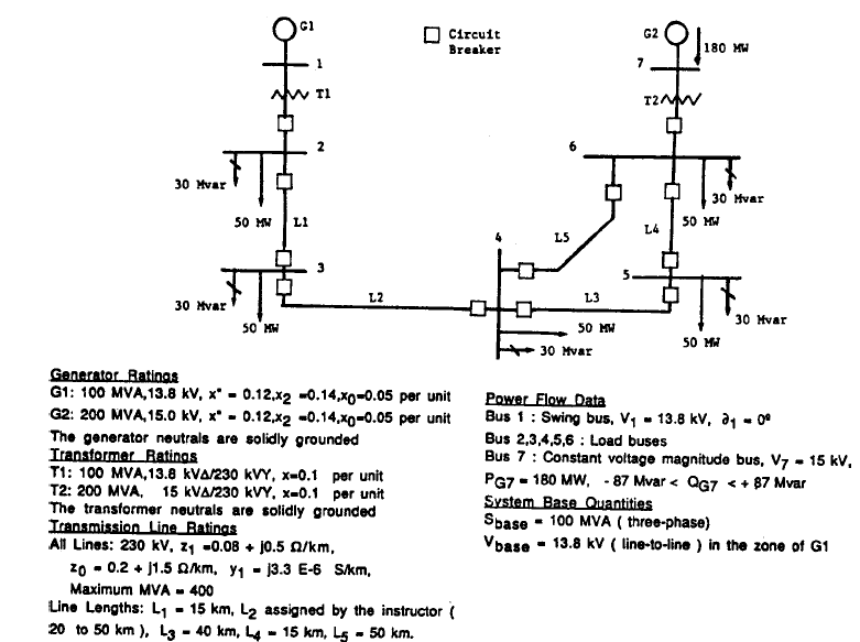
I want to simulate the following transmission loop: enter image description here

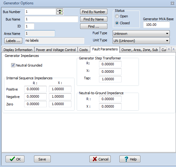
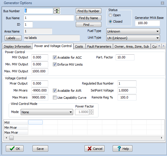
First things first, you see the generator ratings? (\$x_0\$, \$x_2\$ and \$ x^o\$)? How can I implement these data into the simulator? I went through all the options, but I couldn't find anything:

enter image description here enter image description here

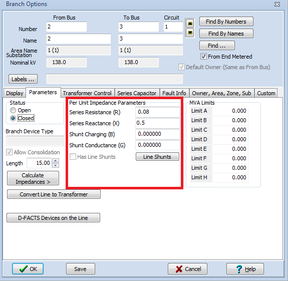
As for the transmission line ratings, I see there are \$Z_0\$ and \$Z_1\$. What are they? And how can I enter these data into the program? There is only one place for one:

enter image description here

In any case, I need someone to simulate this program using the PowerWorld software and upload it.

(Note: all data should be in per-unit)

EDIT

Whenever I try to run this simulation, I get this message:

enter image description here

Any clue?

\$\endgroup\$

3 Answers 3

5
\$\begingroup\$

I will try to answer all of your questions. Maybe this will help you:

First, the generator ratings are given as:

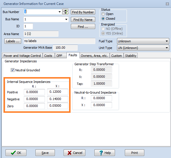
  • \$x_0\$ is the internal zero reactance
  • \$x_2\$ is the internal negative reactance
  • \$ x^"\$ is the internal positive reactance

You can enter these data in the "Fault" window of the "Generator Information for Current Case". Look at the following image:

enter image description here

For the second part, you are wrong! Why did you put the data in Ohm/km? You should put it in per unit. Also, you already have the line lengths in km. It should be easy for you to calculate. I will do the first as an example.

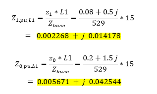
The positive/zero sequence impedance can be found by dividing the given values by the the \$ Z_{base} \$, and then multiply it with the line length:

enter image description here

This is just for the first line, you can do the same for the other.

Also, you can enter the positive impedance in the "Parameter" window, and the zero impedance can be entered separately in the "Fault Info" window.

Third, regarding the system blackout. What is your tap ratio in the transformers side? Remember, the typical value for the tap-ratio is between 0.9 and 1.1. Otherwise, the system will not run!

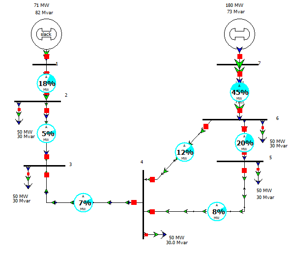
I already simulate your system, and I think it is easy. You can do it by yourself. The system should look like this:

enter image description here

The voltages in all buses should be around 1-pu. I hope this was helpful. You can ask me if you have any question.

Read this file for more information about PowerWorld.

\$\endgroup\$
3
  • \$\begingroup\$ Thanks, that was a good answer. But I have one last question. How can I calculate the Shunt Charging (B) and the Shunt Conductance (G)? \$\endgroup\$ Commented May 26, 2013 at 11:29
  • 1
    \$\begingroup\$ \$B\$ is the imaginary part of the admittance (\$Y\$), and \$G\$ is the real part. Please, remember that the admittance (\$Y\$) is given as: \$Y=G+jB\$. Read: en.wikipedia.org/wiki/Admittance \$\endgroup\$ Commented May 26, 2013 at 14:22
  • \$\begingroup\$ Excuse me but how did you get 529 as your Z base? \$\endgroup\$
    – Jorge Leon
    Commented Nov 28, 2018 at 21:34
4
\$\begingroup\$

I think you may be mistaking x^0 for x" - your document quality is poor so I'm doing my best to decipher. x" is probably a shortened version of x"d which is "generator direct axis subtransient reactance". x0 on the other hand is "generator zero sequence reactance". x2 is "generator negative sequence reactance".

Here is a paper that deals in how to calculate them. I don't know if this helps work out numbers to plug into your program but it might be a step on the way Here is another paper that is informative about the wonderful world of power generation and generator impedances.

\$\endgroup\$
3
+50
\$\begingroup\$

As Andy aka wrote, there is x" (xd") which is sub-transient reactance in d-axis of the generator and it is the basis machine parameter and should be allowed to enter (I can't believe it is not). This value is required if you're going to simulate short-circuits, so maybe it is allowed to insert in other tab (it should be in "Fault").

The other idea is that you inserted a generator-transformer unit while you should insert a generator only.

However, if you're going to calculate power flows, this value is not necessary and can be omitted (so why then is it given on your picture?).

Because the text on the picture says something about "power swings", perhaps you are to simulate swings, so no xd" should be used but xd' rather. Typically the xd' is about 1.5-2 greater than xd", for 100-200 MVA generators xd" = 0.25, (for smaller units it can be 12%), xd' = 0.4, so obviously data given is not xd'. (Maybe "power swings" text is only to tell that the busbar is not a reference node).

The values of "Internal Sequence Impedances" are: negative - use x2, zero - use x0, and perhaps x" could be positive seq., however it should be x1 which is xd and it's usually about 200-250% of the generator's base reactance that you'd calculate from U^2/S (probably you need to convert them to pu's as default value is 1, so type just what you have on your picture).

For the line sequence impedances they are given on your picture as eg. 0.2+j0.5 Ohm/km, so you calculate line reactance as 0.5 Ohm/km multiplied by line length, as well as resistance and also capacitance given as y = 3.3e-6 S/km, so multiply by line length.

EDIT

It mostly depends on what kind of simulation you would like to perform. Perhaps the software you're using has two modes of operation, Power Flow and Transients or something like this. In the first case, as I've written above, you'd not need xd" so you are not allowed to input it. Perhaps you should only switch the simulation type from "static" to "dynamic".

However, you have not provided any information about the type of your simulation (there is no question on the picture, either).
\$\endgroup\$
2
  • \$\begingroup\$ I choose x" to be a positive sequence impedance. This was the only option for me. Anyhow, there is no question given in the picture, because all I want to do is just to simulate this specific system using PowerWorld. Nothing more. My problem here is how to enter these data into the *.PWB file. I tried many many times, and I am always getting this message: i.imgur.com/LRBDGxt.png?1 Argh, really don't know what is the problem. BTW, you can download this software and try it for free. Thanks \$\endgroup\$ Commented May 13, 2013 at 13:35
  • \$\begingroup\$ Using xd" instead of xd would be a mistake in power flow calculations. In my opinion you get a black out because there is no external system (equivalent Thevenin reactance), you might need to add one even if connected to generators with large impedance. Perhaps it isalso required to do some pre-calculations (initial state of differential eqns.) \$\endgroup\$
    – Voitcus
    Commented May 13, 2013 at 14:51

Your Answer

By clicking “Post Your Answer”, you agree to our terms of service and acknowledge you have read our privacy policy.

Not the answer you're looking for? Browse other questions tagged or ask your own question.