We are unable to generate a sine signal properly using a MC68HC908GP32 microcontroller. PWM description begins in page 349. Clock frequency is 2.4MHz, while we have used 7 kHz PWM by using the prescaler and setting the timer modulo to 350 as follows:
T1SC = 0x60;    // Prescaler: Div entre 64
//Counter modulo = 0x015E = 350
T1MODH = 0x01;   // High
T1MODL = 0x5E;   // Low
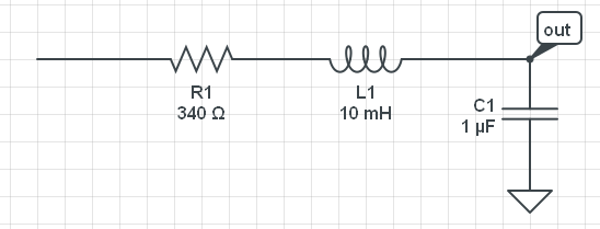
The PWM output is filter by the following RLC filter, and then DC is removed using a series 1uF cap. The cutoff frequency is way below PWM's 7kHz.

First, we have tried using a LUT, which samples were generated using this site (100 samples, amplitude = 250). This comprises a single period.
int seno[100]={ 125, 133, 141, 148, 156, 164, 171, 178, 185, 192, 198, 205, 211, 216, 221, 226, 231, 235, 238, 241, 244, 246, 248, 249, 250, 250, 250, 249, 248, 246, 244, 241, 238, 235, 231, 226, 221, 216, 211, 205, 198, 192, 185, 178, 171, 164, 156, 148, 141, 133, 125, 117, 109, 102, 94, 86, 79, 72, 65, 58, 52, 45, 39, 34, 29, 24, 19, 15, 12, 9, 6, 4, 2, 1, 0, 0, 0, 1, 2, 4, 6, 9, 12, 15, 19, 24, 29, 34, 39, 45, 52, 58, 65, 72, 79, 86, 94, 102, 109, 117};
The width of the following pulse is computed every PWM cycle:
interrupt 4 void rsi_t1ch0 (void)
{
    //-- disable interruption flag
    T1SC0&=(~0x80);
    //-- pwm to '0'
    PTB&=0xFD;

    //some sensor measures are done here.... 100 out of the 350 cycles are left for this
}
/************************************************************/
/* TIM1 overflow rutine                                     */
/************************************************************/
interrupt 6 void rsi_ov1 (void)
{

    T1SC&=(~0x80);
    //-- set PWM to 1
    PTB|=0x02;
    T1CH0H = ((seno[fase])>>8);   // high bits
    T1CH0L = (seno[fase])&0xFF;   // low bits
    fase+=1;
    if (fase >= 99)
      fase=0;
}

void main(void)
{
float temp;
    int i;

    CONFIG1|=0x01;
    DDRB=0xFF;      //-- Port B is set as output
    PTB=0x00;
    //Timer setup
    T1SC = 0x60;    // Prescaler: Div by 64
    T1MODH = 0x01;   //Counter modulo
    T1MODL = 0x5E;
    T1SC0 = 0x50;  //Comparator setup
    //-- Initial width
    T1CH0H = 0x00;
    T1CH0L = 0x53;

    EnableInterrupts;
    T1SC&=~(0x20); //Run timer forever
    for(;;);
}
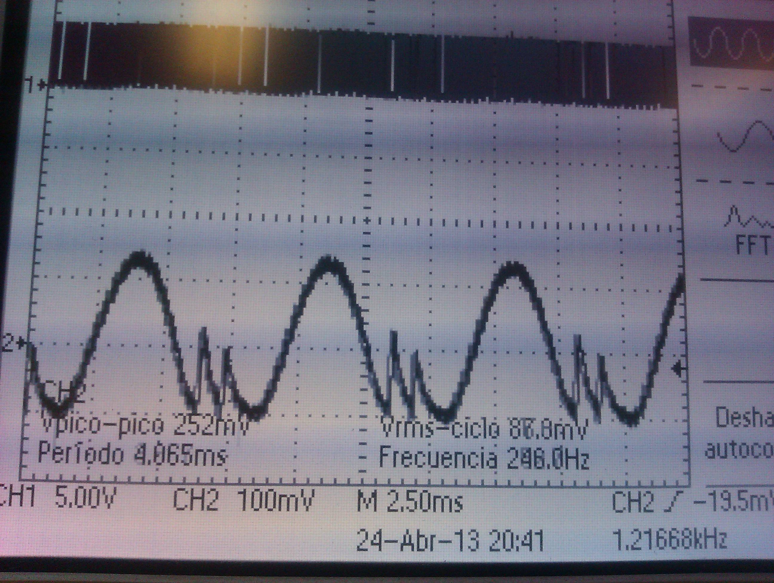
When pluggin it into the scope, we get the following signal. We are unable to avoid that strange peak near the minimum.

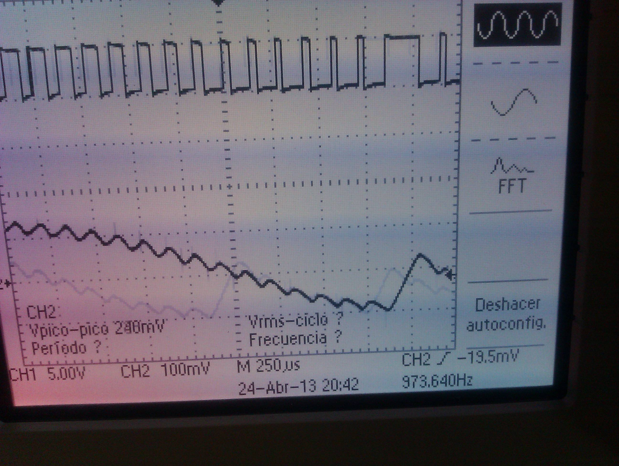
When zooming around that peak, we can see how the PWM output (up) is in fact incorrect.

So, after messing around for a while and being unable to get rid of it, we have tried computing the sine signal in the MCU, instead of hard coding the value for each sample. We have added the following code in the main function, just before all the counter setup:
 for(i=0;i<99;i++) {
     temp=100*(sin(2*3.14159*i/100)+1);
     seno[i]=(int)temp;
 }
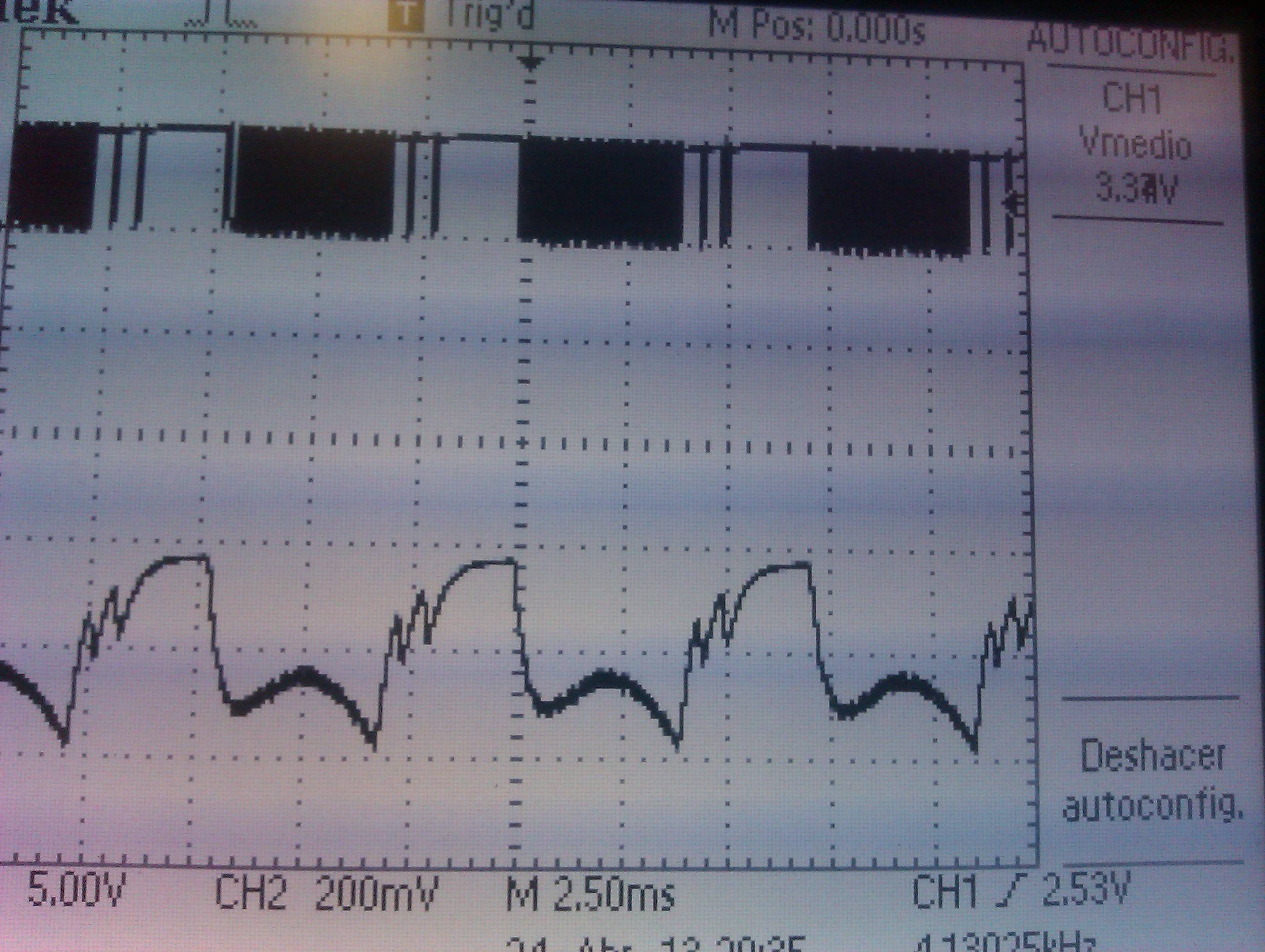
But results don't even look like a sinusoid:

After hours struggling with it, we haven't been able to find our mistake. We would appreciate a piece of advice.
