I have a question regarding some conducted RF immunity (IEC 61000-4-6) tests. We inject noise starting at 150kHz until 80MHz. The signal injected is AM at 80%. The level is 20Vrms.
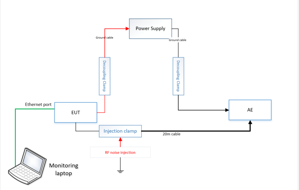
Here is the setup of the test:
In our setup, both unit and auxiliary equipment are floating, there is no direct path to ground. The cable being tested consists of a power conductor, a ground conductor, and an RS-232 line. Our goal is to assess the margin of our one-wire communication (RS-232.)
The power supply is designed to generate a voltage drop across the negative terminals of both the equipment under test (EUT) and the auxiliary equipment (AE.) This setup allows for a circulating current. Additionally, the RS-232 data line is connected to a CMOS that shares the same ground as previously mentioned.
If any additional current is introduced to the existing circulating current, it will impact the input of the CMOS. This outcome will result in a failure.
We did the test four times at 20Vrms and we got a fail (temporary loss of data) at 3.5MHz and 3.65MHz. When I convert this to a wavelength the cable's length is exactly a quarter wavelength. (3.5MHz -> 80m).
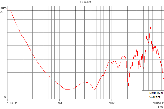
Here is a graph of a current probe monitoring the current 10cm away from the EUT. 
I can deduce that from 100kHz to 4MHz the system behaves like an inductor. Another observation is that at the critical 3.65MHz the system sees close to an open circuit, which would mean that the standing waves are the highest and hence some resonance.
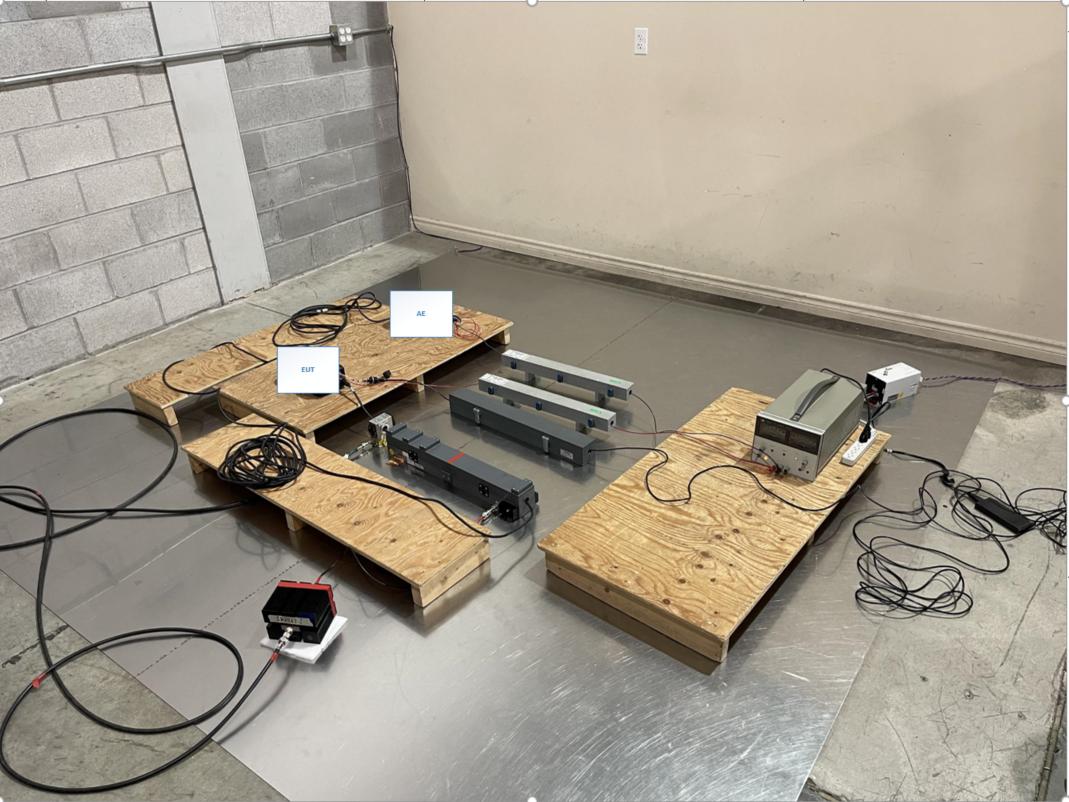
I would like to get some help maybe visualizing a bounce diagram or some other way in order to understand how is the energy flowing in the system, and what causes these fails at the above mentioned frequencies. Just to be clear. I do not need suggestions to solve the problem of “fails”. Thank you Here is the setup in the lab:


