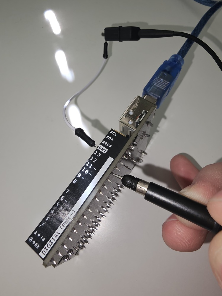
I've just purchased my first oscilloscope, a Siglent SDS1202X-E, and am experiencing an issue with a square wave signal generated from an Elegoo Uno R3 board. I've calibrated the probes, and I'm quite confident that the issue isn't with the scope itself.
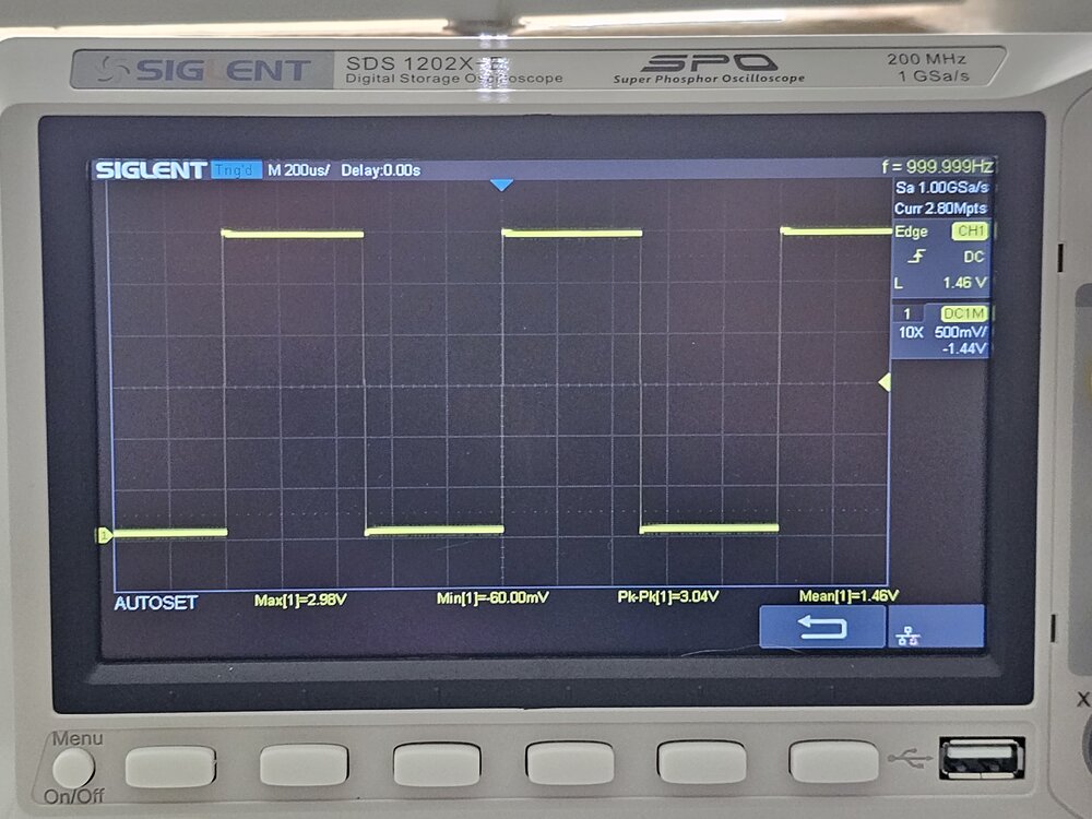 Figure 1: What I believe is a properly calibrated square wave.
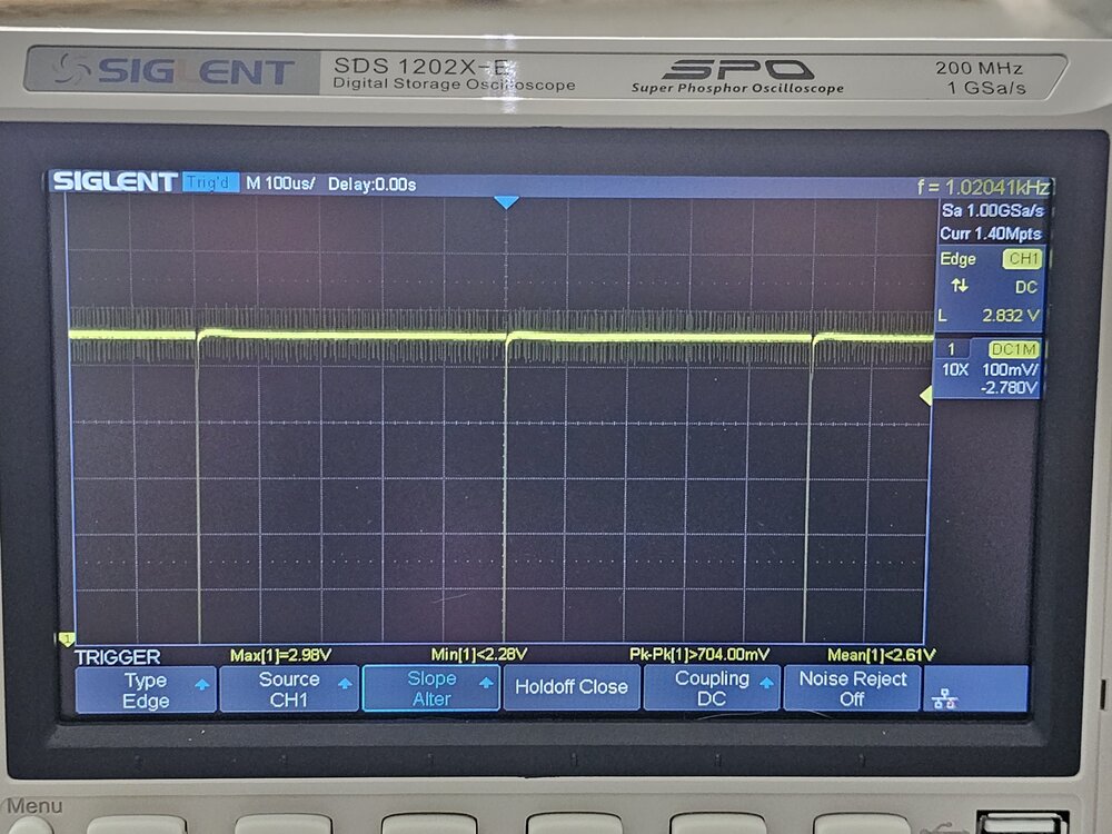 Figure 2: Part of the calibration process. Here's the video I followed. https://www.youtube.com/watch?v=0JnyLoD06rM
The Issue
When generating a square wave at 60Hz using the Arduino board, there's a significant amount of overshooting/undershooting and ringing. This issue is obsered regardless of the frequency of the square wave (I've tested it at 15Hz, 60Hz, 480Hz, and others).
While I understand some of this is expected, the level I'm seeing (3V off a 5V signal on both the rising and falling edge) seems excessive. This deviation remains consistent across all tested frequencies.
Here are some images of the waveform:
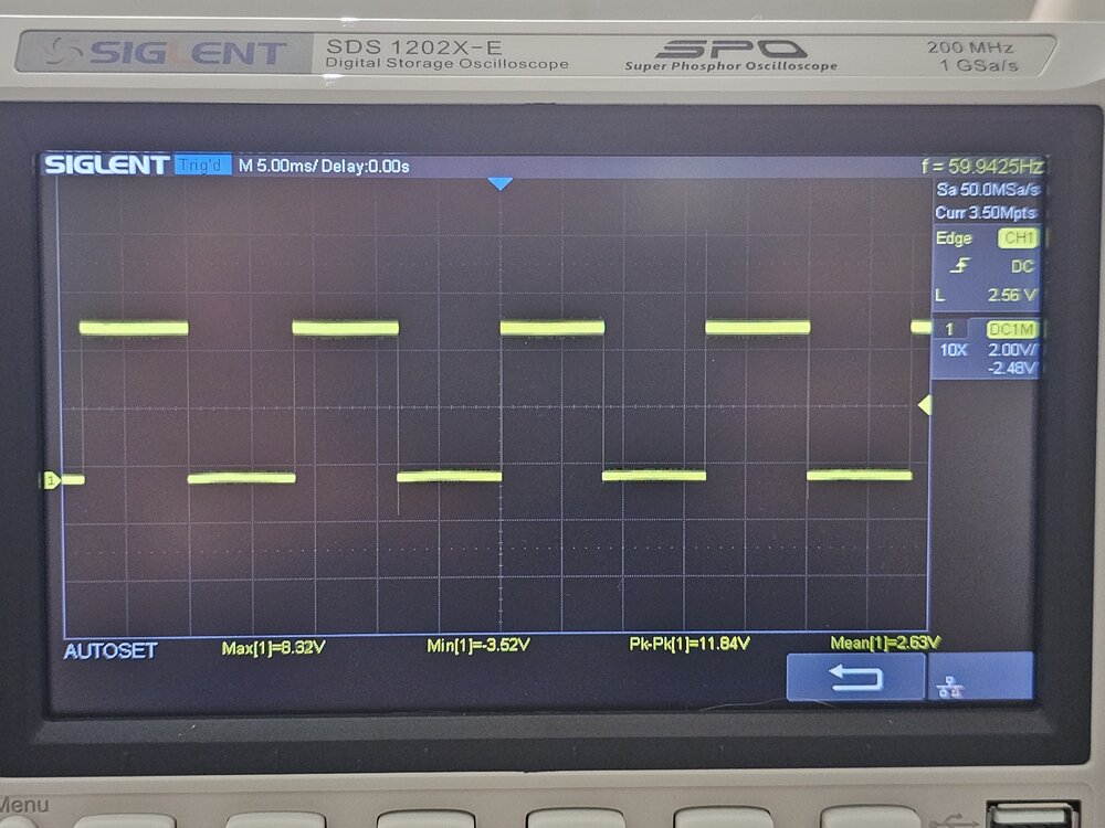 Figure 3: Waveform at 60Hz. The overshoot/ringing is brief, but substantial.
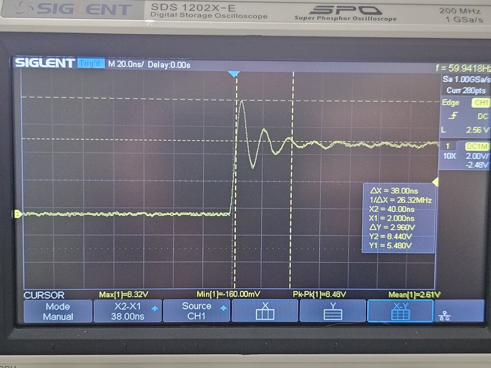 Figure 4: Close-up of the waveform, showing the magnitude and duration of the overshoot/ringing.
Code Generating the Waveform
Heres the code I used to generate the square wave:
#define REFRESH_RATE 60

void setup() {
  pinMode(12, OUTPUT);
}

void loop() {
  unsigned long period = 1000000 / REFRESH_RATE; // total period for one cycle
  unsigned long halfPeriod = period / 2; // half period

  unsigned long start = micros();

  digitalWrite(12, HIGH);
  while (micros() - start < halfPeriod); // delay for half period while HIGH

  digitalWrite(12, LOW);
  while (micros() - start < period); // delay for remaining half period while LOW
}
This code sets the 12th pin as an output and generates a square wave signal with a refresh rate of 60Hz.
Troubleshooting Steps
So far, I've tried the following to resolve the issue.
- Updated the oscilloscope's firmware.
- Compensated the probes.
- Calibrated the scope.
- Set the probe to 10X on both the oscilloscope and the probe itself.
Used the ground spring that came with the probe.
Edit- Initially used the included ground spring, connecting it directly to ground, and the probe tip directly to the Arduino pin contact. This approach improved the situation, yet it didn't fully resolve the issue. Any use of an intermediary wire, whether between the ground spring and the ground, or between the probe tip and the circuit contact, led to the problematic results described earlier.
- Despite using the ground spring correctly the circuit still produced a significant overshoot/undershoot (regarding the setup) of 1V on a 5V 10Hz/60Hz/480Hz square wave signal. This shows that while the ground spring helped, it wasn't a complete solution.
- Powered the microcontroller with a 9v battery.
- Turned off all other nearby devices that may create electromagnetic interference.
- Ensured the oscilloscope probe cable is straight and not coiled.
- Bypassed the wires typically inserted into the microcontroller holes and connected the oscilloscopes probes directly to the contacts underneath.
- Moved the oscilloscope probes closer and farther apart from each other.
- Tried the same setup with a different board (Elegoo Mega 2560 R3).
Despite these steps, the problem persists. I would like to attribute this to cheap probes or similar issues. However, considering the clean square wave generated at 1KHz by the built-in generator and that I've tried connecting the oscilloscope probes directly into the Arduino contacts with no wire intermediaries, I'm at a loss as to the cause of this issue.
Question
Can anyone provide insight into why this overshooting/undershooting is happening, and suggest possible solutions to reduce it? Is this a common issue when generating square waves with Arduino boards, or could there be a specific issue with my setup?

