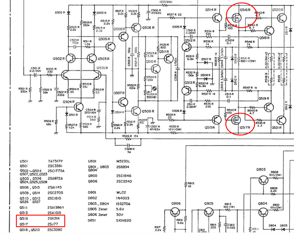
I'm not sure the MOSFETs are the problem. Basically, with power off, put the multimeter in diode-check mode and you should see a 0.7 V diode from Source to Drain or D-S on both. Then measure resistance from S-G and both should be similar. If that seems good, then it will have to be removed to test further. See How to Bench-Test an N-channel MOSFET for ideas of how to test the N-channel device. P-channel test is similar but there are some significant polarity differences. Must be removed to function-test because a pin could be open and that won't be obvious in-circuit.
To answer the question about replacing them, what you want to match, as closely as possible in a MOSFET, are these parameters. This isn't an exhaustive list, but should be enough to start the (long) journey in looking for a suitable replacement:
- Package. There is a little leeway in this, such as a TO-92 being physically similar to a TO-18. What won't be as easy, is replacing a TO-92 with a TO-3 for example. Here is a list of Transistor Outline packages by EEsemi.
- Pin Order. DSG, DGS, GSD, GDG... any combination likely exist. Ensure that a replacement will actually mount in place of the original. May find several that would match if rotated or placed on the other side of the board, which is usually not acceptable. Have swapped legs before... not recommended but if no other choices exist, judicious usage of insulator tubing is recommended.
- \$V_{DS}\$ Drain-Source Voltage. This is how much voltage the D-S channel can withstand before avalanche failure (short.) Must be equal or greater than existing.
- \$V_{GS}\$ Gate-Source Voltage. This is what voltage range can be applied to the gate. Most are around +/-15 Volts but be aware that some can be different. Exceeding the gate voltage will destroy it.
- \$I_{D}\$ Drain Current. How much current can pass through it. Must be near the original value else it will overheat.
- \$P_{CH}\$ Power. May see these values in peak and average values, such as 30Wp and 2W. Focus on the average; just find something close (don't replace a 2W part with a 1W part - it will overheat.)
- \$V_{GS(ON)}\$ Gate-Source "On" Voltage. This is the threshold voltage applied to the gate where current just begins to flow in D-S. Most MOSFETs have a Vgs of 6 V or more. So-called "logic-level" MOSFETs have a Vgs of 2-3 V, so can work with common digital voltages. These particular devices have a very low Vgs, so might be challenging to match.
- \$C_{ISS}\$ Input Capacitance. This is the capacitance of the gate. These devices are very low (90pF / 0.09nF / 0.00009µF) which makes them well-suited to very high-speed amplification. A replacement that had significantly more Ciss would likely still work, but not as well at high frequencies. More gate capacitance could also cause ringing or oscillation - will have to probe with an oscilloscope to see it (in the MHz range, causing them to overheat.)
Thermal imagers are becoming more commonplace. Recommend using one at start-up to see what gets warm and how much. Burning fingers is not fun!
There are some cross-reference websites out there which might help. Still compare the datasheets however (datasheets have the final word.)
Amplifiers by their nature, are finely-tuned to their components. Changing any component could impact performance. To re-tune such an amplifier is a rather complex task. But if you change the MOSFETs and performance degrades, search for another question here about the exact symptoms - chances are good that someone else has experienced similar.

