1
\$\begingroup\$

I am utilizing the AMS1117-3.3 voltage regulator to convert a 5V input to 3.3V. Following the schematic provided in the datasheet, I have added a couple of LEDs to the circuit.

However, I am encountering an issue where both LEDs illuminate when I connect a 5V source (which is the expected behavior). Surprisingly, even when I connect a 3.3V source from other pins, both LEDs continue to light up.

I am seeking assistance in finding a solution where, when powered by 3.3V, only the 3.3V power LED illuminates.
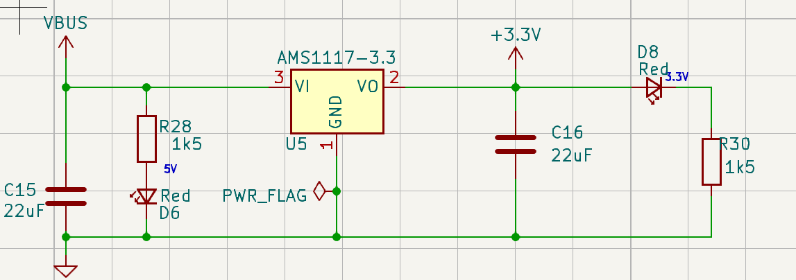
Schematic Is there a way to achieve this without experiencing significant voltage drops? Any suggestions would be greatly appreciated

\$\endgroup\$
7
  • \$\begingroup\$ Let me check if I got it right: If you apply 3.3V externally across VO and GND terminals without applying 5V across VBUS, D6 lights up. Correct? Sorry if I couldn't understand correctly. \$\endgroup\$ Commented Jun 15, 2023 at 12:47
  • \$\begingroup\$ Yes. When connecting 3.3V, both light up. However, this should not happen. \$\endgroup\$
    – Y-E-Quit
    Commented Jun 15, 2023 at 12:50
  • 2
    \$\begingroup\$ If the rest of the circuit will be happy with, say, 3.1V then you can add a low Vf diode (e.g. Schottky) from VO pin to 3.3V. This will prevent current flow back into the regulator when an external power is applied. \$\endgroup\$ Commented Jun 15, 2023 at 12:57
  • 1
    \$\begingroup\$ Why are you connecting 3.3v to what should be the output of a voltage regulator? \$\endgroup\$
    – HandyHowie
    Commented Jun 15, 2023 at 12:57
  • 1
    \$\begingroup\$ @HandyHowie I saw a few circuits having MCU in which the programmer provides 3.3V and this goes directly across the output of a linear regulator. So the OP's could be a possibly similar scenario. \$\endgroup\$ Commented Jun 15, 2023 at 13:00

1 Answer 1

1
\$\begingroup\$

You could also place a diode on the regulator's input side to prevent the input LED from lighting up from any leakage currents. Just be sure to move the cap to the regulator's input pin side. The TI version (LM1117) datasheet shows a similar example when using two regulators in a battery backup arrangement, (see figure 9-7). Also be aware that if passing a high current you could come close to the regulator's drop-out voltage requirements, so a Schottky type diode will be best to use in this case.

\$\endgroup\$

Your Answer

By clicking “Post Your Answer”, you agree to our terms of service and acknowledge you have read our privacy policy.

Not the answer you're looking for? Browse other questions tagged or ask your own question.