0
\$\begingroup\$

I would like to change a crystal oscillator circuit to an oscillator IC like this. Below is the image of the original crystal circuit.
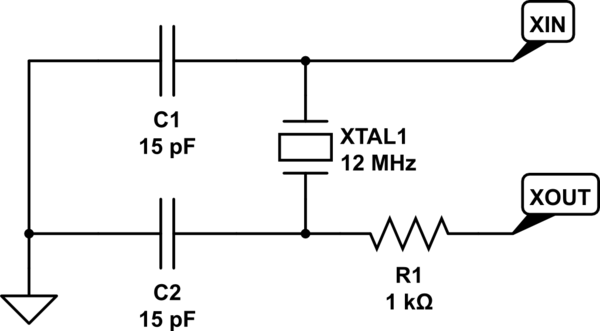
schematic

simulate this circuit – Schematic created using CircuitLab

I am not really sure how to connect them. I would assume that the output pin of the oscillator IC would just go to XIN pin, but what do I do with the XOUT? I would also assume that they would need decoupling capacitors. What do I do with the resistor in the XOUT of the original circuit?

Are oscillator ICs less reliable than crystal circuits in terms of longevity? Are they more prone to breaking?

\$\endgroup\$
2
  • \$\begingroup\$ Does your device support using an external oscillator like that? Not all of them do. \$\endgroup\$
    – Hearth
    Commented Jun 16, 2023 at 15:41
  • \$\begingroup\$ @Hearth The chip is the rp2040 and it seems to be able to accept oscillator IC \$\endgroup\$
    – DrakeJest
    Commented Jun 16, 2023 at 20:03

1 Answer 1

2
\$\begingroup\$

In your existing device (MCU or similar), XIN and XOUT typically connect to an amplifier onboard the chip. The input to XIN is amplified with the right phase inversion, sent through XOUT, and filtered via the crystal back to XIN to produce positive feedback into the amplifier; that positive feedback produces an oscillation.

Generally, if you want to use an external oscillator and your device datasheet confirms that it's supported, you'll typically connect it to XIN, and you'll leave XOUT disconnected - there is no longer a need for external feedback since the oscillator circuit internally produces feedback. Of course, any recommendations in your datasheet will take precedence.

Your load's datasheet may suggest specific configuration bits that you may want to set to disable the onboard amplifier; e.g. ATMega devices have fuse bits that enable that amplifier.

I'm not aware of a specific trend regarding whether ICs or crystals are more robust; in either case there will still be some kind of resonator (which could be crystal, MEMS, or otherwise) and a feedback loop, just internal to a single oscillator package.

\$\endgroup\$
4
  • \$\begingroup\$ The chip is the rp2040 and it seems to be able to accept oscillator IC. Do i still need to place a series resistor on XIN to prevent ringing? or is that not a problem for oscillators since they have built in circuit to handle that \$\endgroup\$
    – DrakeJest
    Commented Jun 16, 2023 at 20:03
  • \$\begingroup\$ @DrakeJest the XIN input should be high impedance; for 1-15 MHz my instinct is to worry about layout quality first. A series resistor upstream of a highZ input won't really attenuate ringing in the same way matched termination might. \$\endgroup\$
    – nanofarad
    Commented Jun 16, 2023 at 20:35
  • \$\begingroup\$ Okay so no resistor is needed if i have a good layout, but how do i make a good layout for a oscillator IC? just place it as close as possible? there is just one wire to connect unlike a crystal where there are 2 that i can match \$\endgroup\$
    – DrakeJest
    Commented Jun 16, 2023 at 20:45
  • \$\begingroup\$ @DrakeJest Short distance, good ground connections, and close decoupling following the oscillator datasheet recommendations are the key points I would focus on. \$\endgroup\$
    – nanofarad
    Commented Jun 16, 2023 at 22:57

Your Answer

By clicking “Post Your Answer”, you agree to our terms of service and acknowledge you have read our privacy policy.

Not the answer you're looking for? Browse other questions tagged or ask your own question.