1
\$\begingroup\$

I have read countless documents and viewed schematics on this subject but am still confused when it comes to physically building a box and running all of the wires correctly and safely.

I drew a very simplified pictorial diagram (shown at bottom of post) to give a better context to my questions.

I have a 2U aluminum cabinet with basically 5 pieces front, back, left, right. and bottom which are all screwed together with M3 screws. Each piece provides two 6-32 ground studs so that AC shorts won't have to travel through the M3 screws. Inside the cabinet I have a 5VDC SMPS and a simple internal analog audio amplifier. The following questions relate to grounding only, the internal analog amplifier could be any amplifier and is not the focus of my questions.

I am getting a reading of 14.7 VAC from AC ground to signal ground when I float the signal ground. If I jump the two together with an alligator clip while the unit is still on and the headphone amp turned all all the way up full blast with no input signal, I can barely hear and noise when the alligator clip is connected and disconnected by tapping it in and out. I expected there to be a very noticeable noise but not at all. With music playing as an input signal, the sound is crystal clear even when I do the alligator test. This makes me think maybe it makes no difference, but is safety an issue?

QUESTIONS:

Scenario 1 In the diagram, see "Scenario 1" isolates/floats the signal ground and uses insulated RCA1 and HEAD1 plugs to prevent the plugs from grounding to the aluminum case. All grounds will be run to an insulated ground star not connected to the case.

When connecting external input sources such as those shown in the diagram, will there be any noise or safety issues caused by floating the ground? Note I have shown an external source using a non-polarized AC cord and another external source using a 3-prong AC plug w/ground.

Scenario 2 In the diagram, see "Scenario 2" uninsulated RCA2 and HEAD2 plugs with metal cases grounding directly to the aluminum case. I will run a separate ground wire from the -5V output of the SMPS to the ground star G1 on this case. Is it necessary to run separate ground wires from each plug to the ground star G1, or will the aluminum case serve as ground without creating ground loops?

Will there be any noise or safety issues when connecting external sources while the AC ground and signal ground connected together?

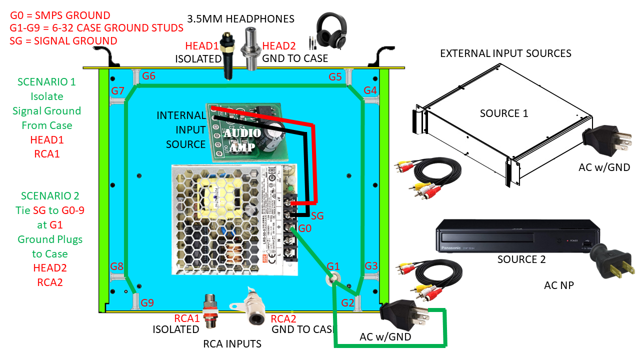
enter image description here

\$\endgroup\$
4
  • 1
    \$\begingroup\$ How to best connect the power supply is in the power supply manual. Is it a MeanWell like in the picture? Which exact model it is? The PSU may have floating output or it may have it connected to earth. Even if output is floating it may be EMI coupled with Y caps to mains input and/or to earth to prevent HF buzzing from the transformer. \$\endgroup\$
    – Justme
    Commented Jun 20, 2023 at 4:52
  • \$\begingroup\$ Thank you for the quick response and information, I have already read the manual for LRS-50-5, and the Y-caps are shown in an internal block diagram and the is no buzzing floated or not as I originally described, I am looking for advice related to the diagram I provided as to which of the two scenarios would be best practice or does it matter. I am trying to determine which plugs to use so that I can drill the holes in the front & back panels. \$\endgroup\$ Commented Jun 20, 2023 at 11:54
  • \$\begingroup\$ Are your questions strictly whether such issues exist, or do you also expect an explanation of why? Do you further expect a conversation regarding what to choose, and perhaps feedback as well once it's tested (or how to test it, for that matter)? Because these questions can be quite complex, it's not clear that you have many options to resolve them (is this a stick-blocks-together design, or a full-schematics-anything-is-open-to-change design?), and poorly defined or conversation-prone questions are unfortunately an ill fit here. \$\endgroup\$ Commented Jun 20, 2023 at 12:24
  • \$\begingroup\$ I agree that the issues are so complex it is practically impossible to ask the right questions. Sorry that It took me a while to reply but I solved the problem by getting rid of the switching power supply and went with a simple step-down transformer, full wave bridge and capacitor. Now It is noise free. I ended up floating the audio grounds. \$\endgroup\$ Commented Feb 17 at 15:10

1 Answer 1

1
\$\begingroup\$

I solved the problem by getting rid of the switching power supply and went with a simple step-down transformer, full wave bridge and capacitor. Now It is noise free. I ended up floating the audio grounds.

\$\endgroup\$

Your Answer

By clicking “Post Your Answer”, you agree to our terms of service and acknowledge you have read our privacy policy.

Not the answer you're looking for? Browse other questions tagged or ask your own question.