0
\$\begingroup\$

I am using a INA4180-4181EVM to find a suitable solution for measuring 0-2A of current in a DC circuit. In the datasheet, there is no equation given for calculating the current based on the read output voltage. How can I calculate the current?

Datasheet

EDIT:

The maximum current that should be measured is 2A, the maximum heat dissipation is set to 1/3W. Here are my calculations based on the datasheet: $$R_{shunt} < \frac{PD_{max}}{I^2_{max}}$$ $$R_{shunt} < \frac{\frac{1}{3}W}{2^2A} = 0.0833\Omega $$ Meaning that the shunt resistor must not be larger than 0.0833 Ohms in order to satisfy the power dissipation requirement. To get a starting point for the gain selection, my calculations are as follows: $$ I_{max} \cdot R_{shunt} \cdot GAIN < V_{SP}\\ GAIN = \left(\frac{I_{max} \cdot R_{shunt}}{V_{SP}}\right)^{-1}\\ GAIN = \left(\frac{2A \cdot 0.075\Omega}{3.3V}\right)^{-1} = 22$$ Selecting a gain of 20 (and my ADC can read 0-3.3V): $$R_{shunt} = \left(\frac{2A \cdot 20}{3.3V}\right)^{-1} = 0.0825\Omega$$

However, (my understanding is that) by using this value the current is limited to exactly 2A, so it is better to select a value lower than 0.0825 to provide some headroom. I want to test the following values for my shunt resistor to find which one suits my circuit best: 0.070, 0.075 and 0.080.

The current calculation is then done as follows (using Rshunt = 0.08):

float Vshunt = V/20; // Gain reduction, V
float Rshunt = 0.08; // Ohms
float I = Vshunt/Rshunt; // A

Using the EVM board, this seems to match my Fluke multimeter pretty close (have not calculated exact difference yet since I dont have the correct Rshunt value at hand).

\$\endgroup\$

1 Answer 1

1
\$\begingroup\$

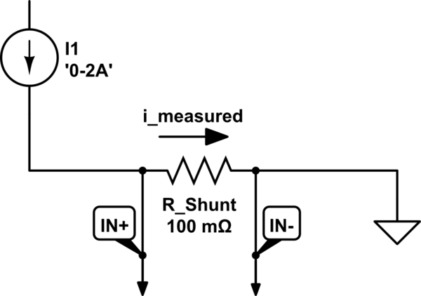
schematic

simulate this circuit – Schematic created using CircuitLab

This circuit technically measures a voltage differential, rather than a current. Each pair of inputs goes into an amplifier with a gain, and so the voltage you read (OUT) is the result of the difference in voltage between IN+ and IN- multiplied by the gain of that device - looks like there are 20V/V, 50V/V, 100V/V, and 200V/V options.

Section 3.1 of the datasheet describes how to use this. You have to use an external shunt resistor, connecting IN+ to the positive terminal of the resistor and IN- to the negative side. The current you are trying to measure should be passed through that shunt resistor which should have a small value. Then, you can use the voltage you measure at OUT to calculate the voltage difference across the shunt resistor, which you can then plug into V=i*R to find i. I'm attaching a rough schematic to illustrate what this looks like, although your actual circuit will be different.

\$\endgroup\$
4
  • \$\begingroup\$ Ok, so lets say I measure 0.95V, have a 1 Ohm shunt resistor and use an IC with 20V/V gain. Is my voltage actually 0.95/20 then? So that my current is I=0.0475/1? \$\endgroup\$
    – eidetech
    Commented Jun 20, 2023 at 14:58
  • \$\begingroup\$ @eidetech Yep, Vshunt=Vmeasured/20, i=Vshunt/Rshunt. You may want to run some trial and error using a load tester or a known current to characterize tolerances/offsets, but the math is pretty much that simple. \$\endgroup\$
    – InBedded16
    Commented Jun 20, 2023 at 18:13
  • \$\begingroup\$ Sweet, thanks. I will try out the chip tomorrow and see if I can get it right. \$\endgroup\$
    – eidetech
    Commented Jun 20, 2023 at 19:10
  • \$\begingroup\$ I have updated the post with my findings now. Do they look reasonable to you? Would love some feedback. \$\endgroup\$
    – eidetech
    Commented Jun 21, 2023 at 13:44

Your Answer

By clicking “Post Your Answer”, you agree to our terms of service and acknowledge you have read our privacy policy.

Not the answer you're looking for? Browse other questions tagged or ask your own question.