0
\$\begingroup\$

I'm a beginner and I'm designing a PCB where I want to power my PCB from a 12-24 V DC car charger. On PCB itself, I want to use 5 V and 3.3 V for different components, so for this purpose I'm trying to find some ways to step down dc voltage from 12-24 V to 5 V.

I searched and found that buck converter, LDO and linear voltage regulators are usually used to step down DC voltages but I have few requirements.

  1. I have an active antenna on my PCB so I want to avoid the use of buck converter because they use inductors and produce magnetic field which can interfere with antenna signals which are usually weak.
  2. I don't want to use linear voltage regulators because they produce a lot of heat.
  3. I couldn't find suitable LDOs in market who can step down 24 V to 5 V without producing much heat. (If someone know any specific LDO which can perform my task, please let me know.)

Personally I want to use buck converter because of their efficiency and low heat dissipation but can someone help me how can I check if magnetic field produced by buck converter will interfere with antenna signals or not? Is there any calculator or formula which I can use to determine the effect? Can I place both of them far (then how far?) to avoid interference.

If you have any other solutions for this problem, please reply.

Thanks a lot!

Edited Part: Below is the Screenshot for the antenna requirements on the pcb board. enter image description here Active antenna receive signals from an L-Band satellite between 1525.0 MHz to 1559.0 MHz

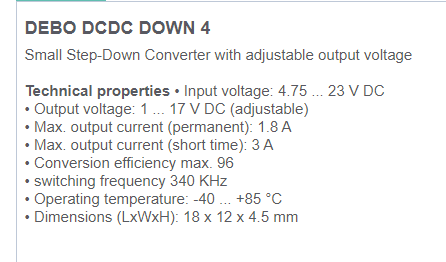
Below is the screenshot for Buck convertor specifying Frequency used: enter image description here switching frequency of Buck Convertor is 340 KHz
\$\endgroup\$
7
  • 5
    \$\begingroup\$ Welcome! It's too general to say you can't use a buck converter and a radio receiver or transmitter on the same PCB. The phone in your pocket have several buck converters and radio transmitter and receivers on the same PCB and functions just fine. You do however have a point in that they can cause disturbance. Due to the high voltage difference, you probably have no other choice than to use buck. Shielded inductors and proper layout will be a good starting point. \$\endgroup\$
    – winny
    Commented Jun 21, 2023 at 8:30
  • 4
    \$\begingroup\$ LDO is a low dropout linear regulator, so it will have the same dissipation as a linear regulator. What is the type and frequency of your radio? If the radio frequency is close to the buck switching frequency or harmonics you might have trouble, however if there is wide spacing in frequency it is much less of a problem. \$\endgroup\$
    – bobflux
    Commented Jun 21, 2023 at 9:40
  • \$\begingroup\$ Is your antenna active at the (typically low) frequencies emitted by the buck converter? If so, would this even be a problem? \$\endgroup\$ Commented Jun 21, 2023 at 13:26
  • \$\begingroup\$ @bobflux I will use an active antenna that can receive signals from an L-Band satellite between 1525.0 MHz to 1559.0 MHz ,switching frequency of Buck Convertor is 340 KHz. \$\endgroup\$
    – Ashish1313
    Commented Jun 21, 2023 at 14:21
  • \$\begingroup\$ You can design a CLC filter with a ferrite bead to make sure harmonics of the switching frequency don't reach the sensitive RF device's power supply. Then you need a good layout with the buck at the other side of the board. There are tons of devices like that on the market. Can you put more info about the buck and RF device you're using? \$\endgroup\$
    – bobflux
    Commented Jun 21, 2023 at 14:42

2 Answers 2

1
\$\begingroup\$

Years ago we used what was called MuMetal as shielding material, put the converter in that box made of that. It is available on line and is not that expensive. You may need feed through filters, not sure. Here is a link to get more information: https://en.wikipedia.org/wiki/Mu-metal

\$\endgroup\$
1
  • \$\begingroup\$ at many 100 MHz, a simple aluminum foil will be just as good or better. \$\endgroup\$
    – tobalt
    Commented Jun 21, 2023 at 19:50
0
\$\begingroup\$

What about a buck converter with a switching frequency of ~2 MHz ? That way, harmonics can't be in your antenna band.

If you do insist on linear regulation, the amount of heat produced will be the same regardless of the regulator, however there are a few ways to manage that heat better:

  • use lowest possible input voltage, because it is the dropout voltage that is dissipated as heat.
  • place diodes in series between the supply and the regulator. That will reduce the heat dissipated in the regulator itself, allowing it to output more current.
  • use an op-amp driving a power transistor as regulator. That way, the current can be very large if you use a transistor that can dissipate lots of heat.
\$\endgroup\$

Your Answer

By clicking “Post Your Answer”, you agree to our terms of service and acknowledge you have read our privacy policy.

Not the answer you're looking for? Browse other questions tagged or ask your own question.