0
\$\begingroup\$

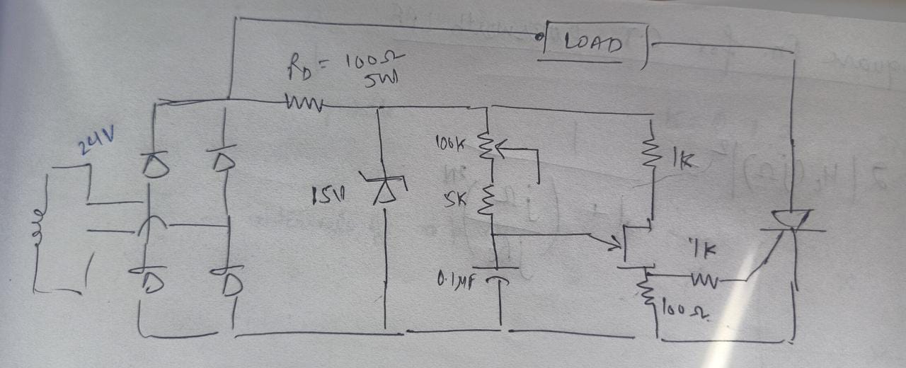
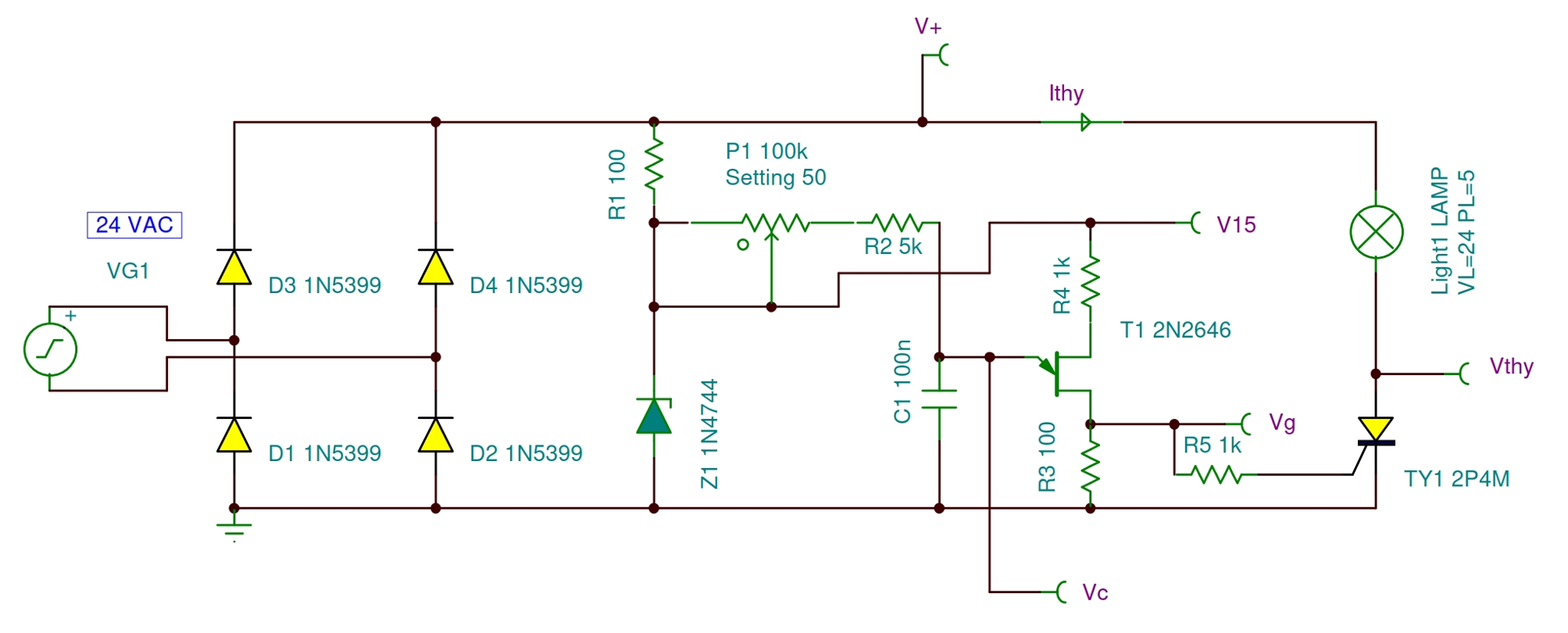
Circuit Diagram: enter image description here

We implemented the aforementioned circuit, and the relaxation oscillator is working fine. However, the load voltage waveform (load hooked with SCR anode) is the same as the rectified supply - the firing angle is zero, and changing the potentiometer doesn't cause any change in the firing angle.

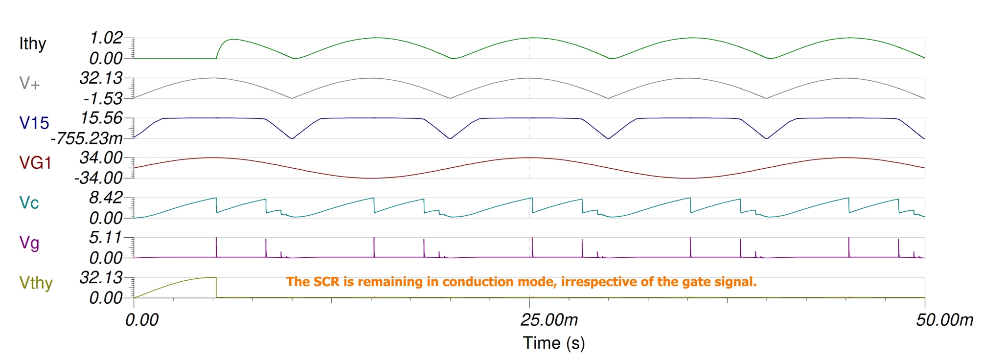
So, the SCR is remaining in conduction mode, through and through, irrespective of the gate signal. We thought that it could be a dV/dt issue, the rate of change of voltage across the SCR is too high, so added a snubber circuit, but that didn't fix anything either. So yep, no solution so far.

A peculiar thing happened however - our professor told us to remove the rectifier, and apply 24V AC supply directly across the zener(we are using a center tapped 12-0-12 transformer for supply). Lo and behold, the firing angle of the SCR is controllable now, although only for the positive half-cycles, of course.

So the half-wave arrangement is working, but not the full-wave rectified one. What could be the issue here?

List of components:

  1. Power Diodes for rectifier: 1N5399 [1 kV, 1.5 A]
  2. RD = Cement-type Resistor [100 Ω, 5 W] (All the other resistors are regular quarter-watt carbon resistors.)
  3. Zener Diode 1N474A [15 V, 1.3 W]
  4. Potentiometer [100 kΩ]
  5. (104) Ceramic Capacitor [0.1 µF]
  6. UJT 2N2646
  7. SCR 2P4M
  8. Load: 30 ohm rheostat
\$\endgroup\$

1 Answer 1

1
\$\begingroup\$

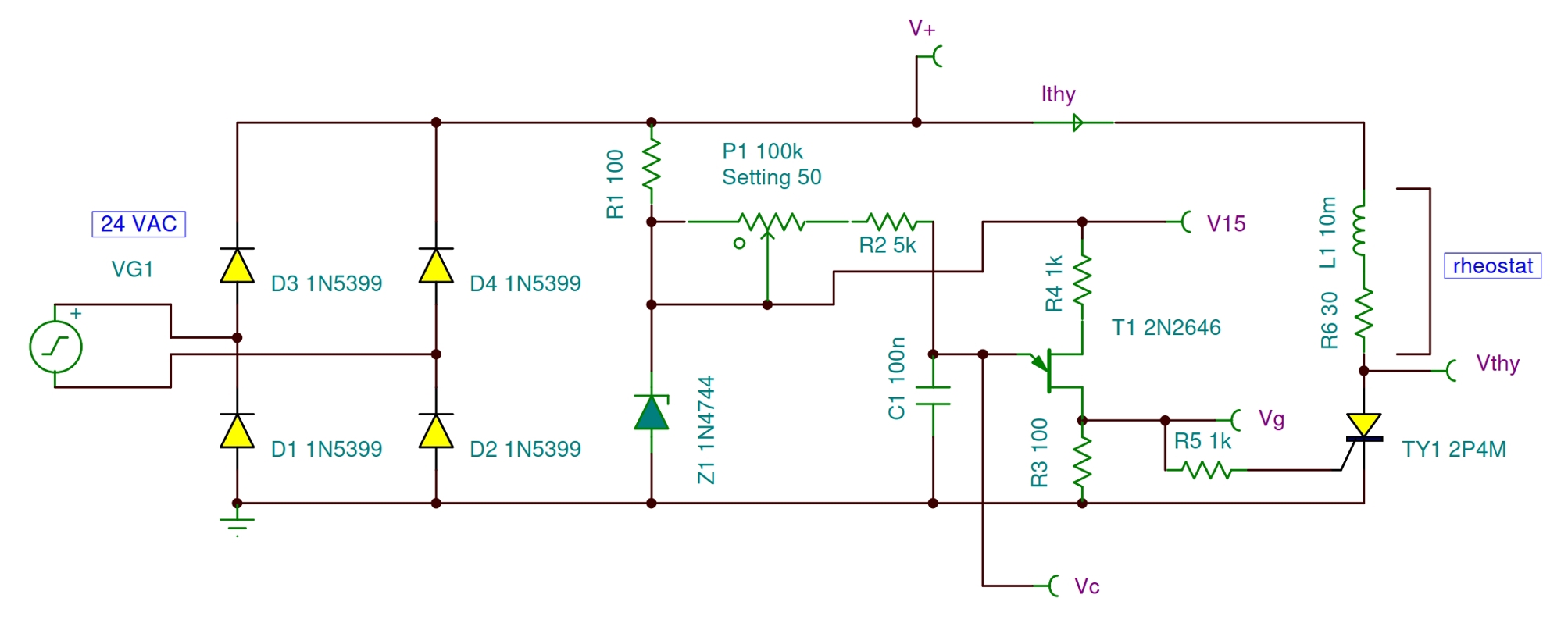
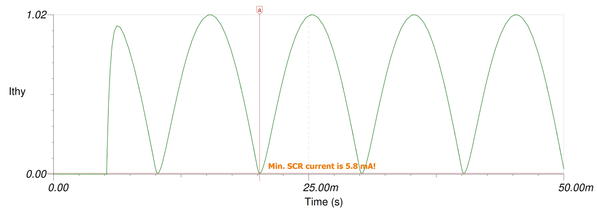
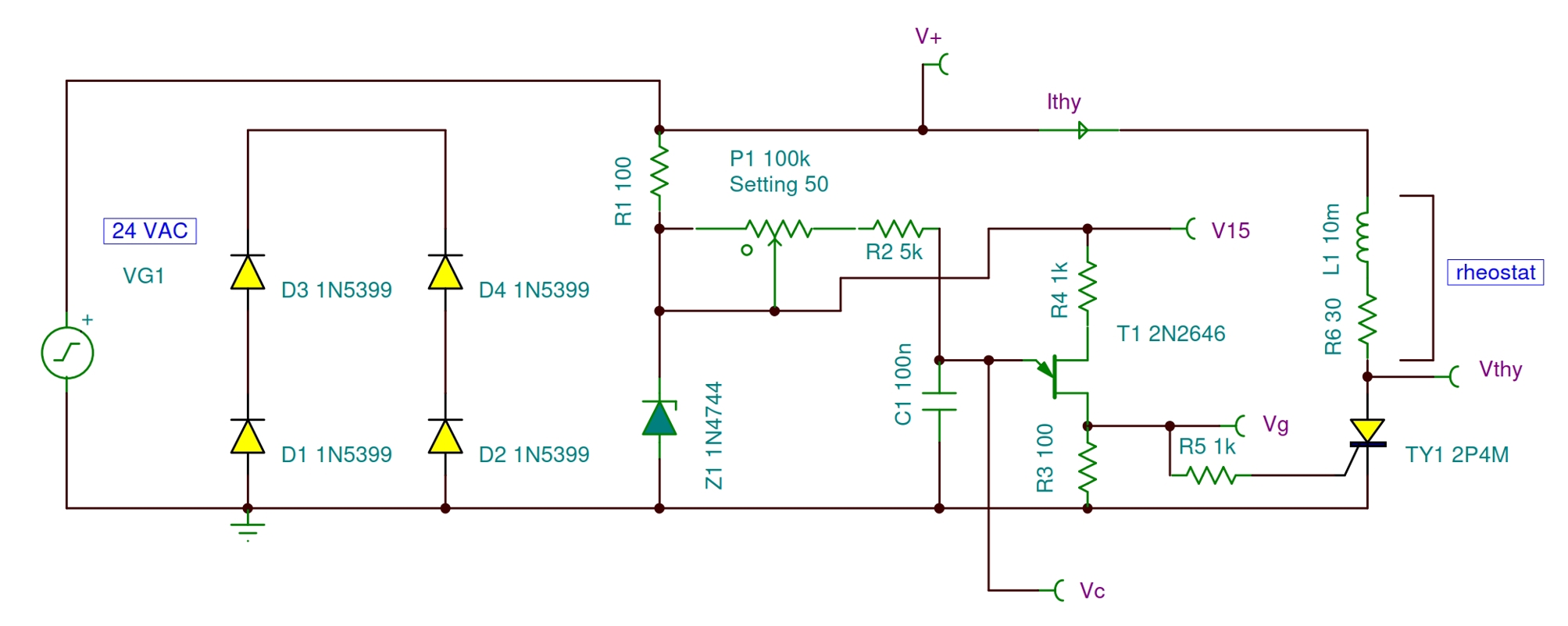
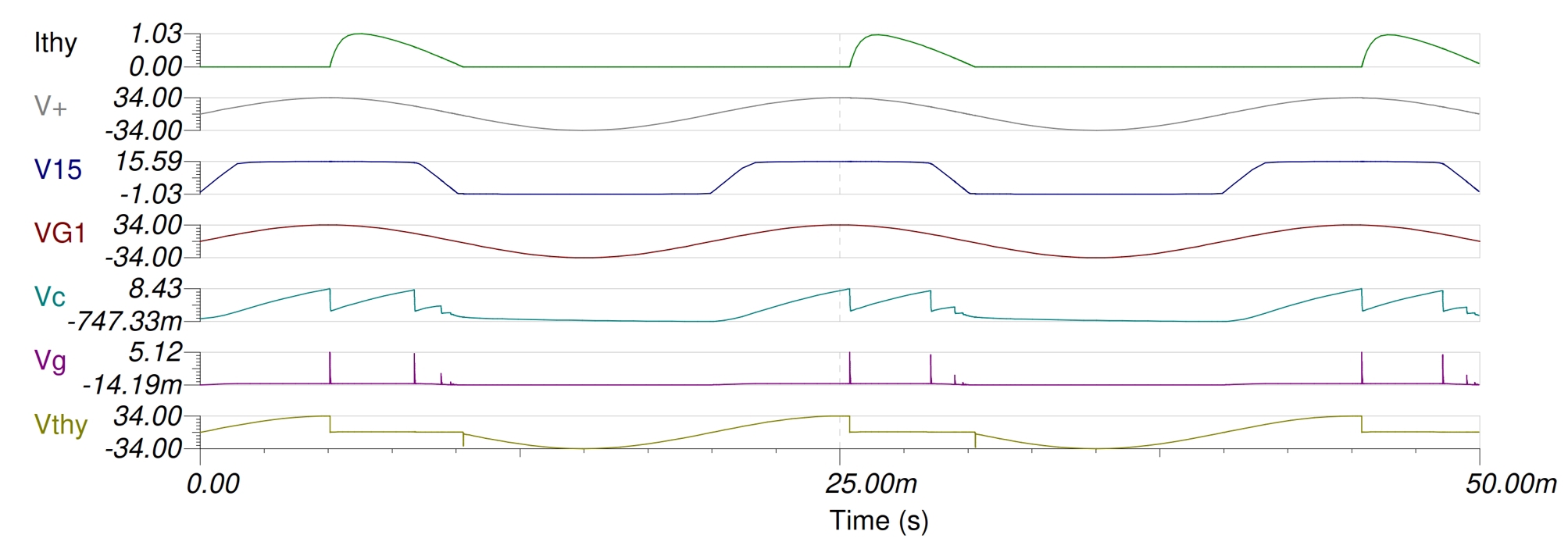
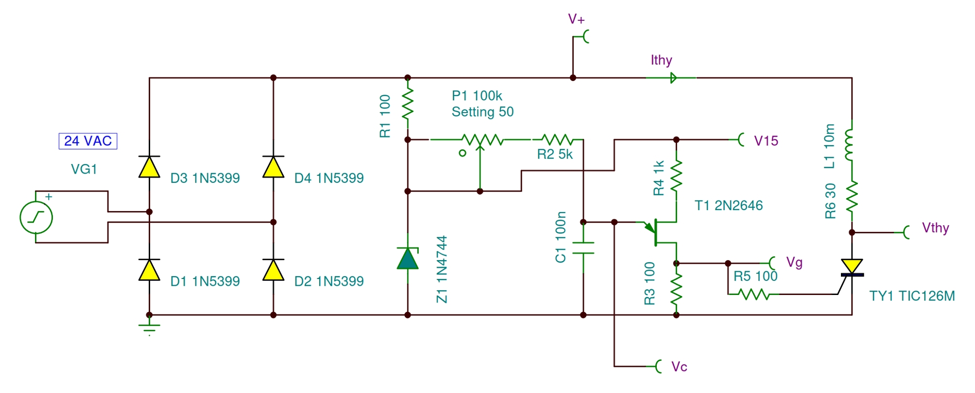
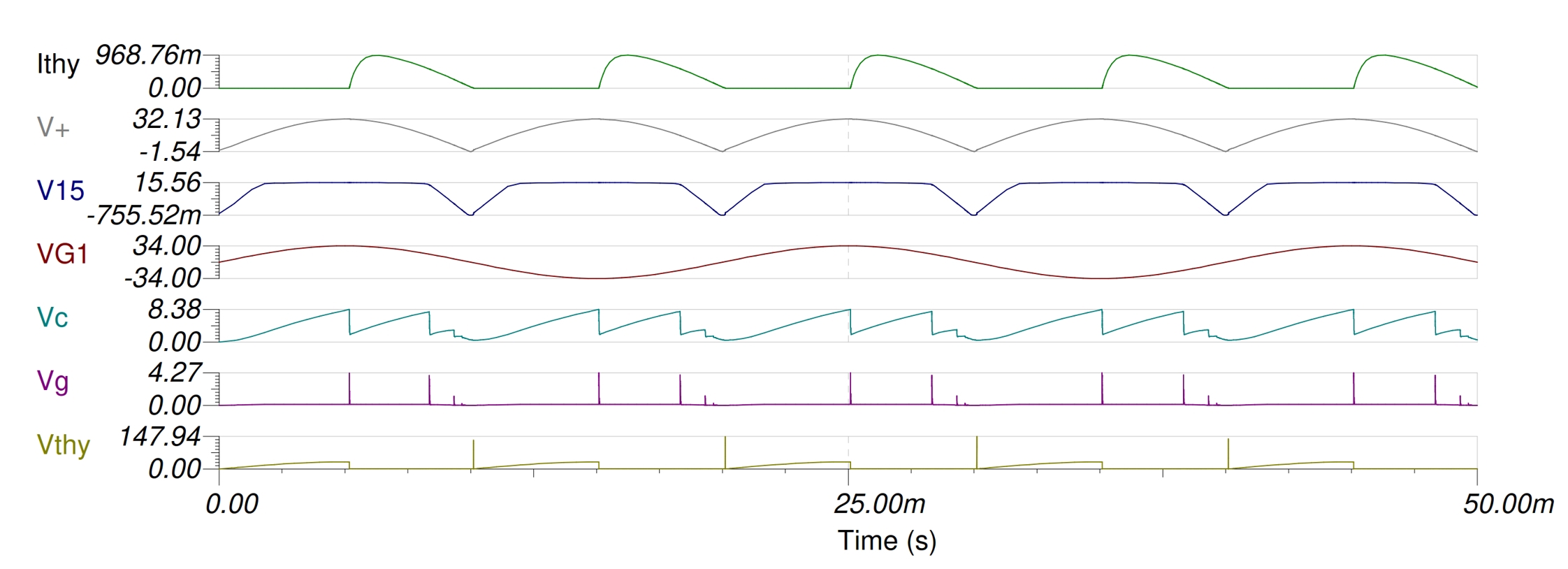
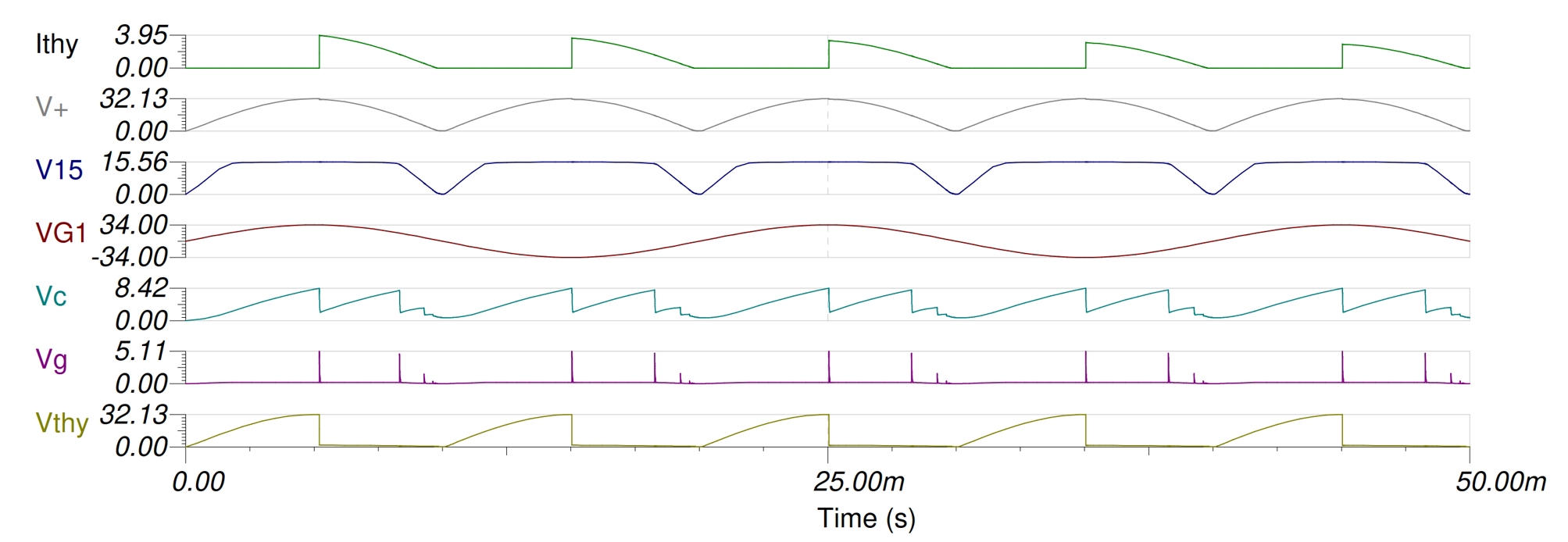
The phenomenon is caused by a combination of two unfortunate circumstances. The first is the use of a thyristor with an unduly low holding current (typically 1 mA) relative to the location. The other is the inductance of the load. Rheostats always have inductance as well as resistance. Since very little holding current is required for the thyristor to stay on, the inductance of the rheostat cannot be neglected. From the simulation example, we will see how the current of the thyristor remains continuously above the holding current under inductive load. First add an inductance to the rheostat. enter image description here enter image description here Let's take a closer look at the current of the SCR and we will see that it is always above the holding current. enter image description here By omitting the rectifier, the SCR current will be reduced to zero and will be controllable in all positive periods. enter image description here enter image description here Since the problem is caused by two factors together, the solution will also be twofold. The simplest will be to replace the SCR with a type that has a significantly higher holding current (e.g. 40 mA). enter image description here enter image description here Alternatively, we can leave the SCR in place and replace the rheostat with a conventional incandescent lamp (24 V 5 W). Its inductance is negligible and we will see the regulation without the need for an instrument. The reason for not using a higher wattage bulb because the cold current would exceed the maximum current of the SCR. enter image description here enter image description here If you observe carefully, the peak current of the SCR steadily decreases as the lamp warms up. The actual current will be much lower, but that requires a relatively long simulation.

\$\endgroup\$

Your Answer

By clicking “Post Your Answer”, you agree to our terms of service and acknowledge you have read our privacy policy.

Not the answer you're looking for? Browse other questions tagged or ask your own question.