2
\$\begingroup\$

I am building a PCB that has a voltage converter at some point. The step down module is configurable if i change one resistor only. The thing is that I want two different voltage outputs that would be configurable by the user.

For example, the voltage converter will "use" one resistor, but if the user changes the selection via a switch, then the previous resistor is "cut-off" from the circuit and the circuit "sees" the other resistor.

You can think of this as a custom potentiometer. I cannot use an existing potentiometer, since I want the values to be specific.

\$\endgroup\$
4
  • \$\begingroup\$ electronics.stackexchange.com/questions/462403/… - header with jumpers is probably the cheapest \$\endgroup\$
    – Mat
    Commented Jul 3, 2023 at 14:12
  • \$\begingroup\$ Thank you Mat! I want a more professional looking approach, so I am thinking going with DIP switches... Is there any reference for how it should be connected? \$\endgroup\$ Commented Jul 3, 2023 at 14:16
  • 1
    \$\begingroup\$ Always connect the resistor with the higher value and optionally connect another resistor in parallel via switch. or use 2 resistors in series and bypass one by switch. \$\endgroup\$
    – Jens
    Commented Jul 3, 2023 at 14:18
  • \$\begingroup\$ Please note that in any of the scenarios posted, the switch cannot be reliably activated "on the fly" when the supply is on. Since pretty much every switch has some manner of electromechanical bounce which would in turn cause oscillations on the voltage supply. To avoid such and allow switching on the fly, maybe connect the switch through a RC lowpass filter to an analog switch and have that one pick resistance. \$\endgroup\$
    – Lundin
    Commented Jul 4, 2023 at 14:08

3 Answers 3

11
\$\begingroup\$

The step down module is configurable if i change one resistor only.

So, the switch will change the feedback resistors of the converter.

The circuit given in Davide's answer causes a momentarily open during the position change of the switch. This can cause the output to change drastically, before bringing to desired level. Depending on the application, this can cause some problems on the load side. The behaviour totally depends on the design i.e. the output may not change (rise or fall) significantly that fast, but still there's a risk.

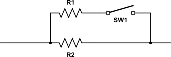
The solution is to keep one resistor, and add the switchable one in parallel:

schematic

When the SW1 is open the feedback will see R2 only, when it is closed the feedback will see R1 || R2 which is lower than both therefore changing the output voltage.

As stated in Davide's answer, SW1 can be jumper pads or any type of mechanical switch, or even analog SPST switch which can be activated or deactivated using logic signals.

\$\endgroup\$
5
  • 1
    \$\begingroup\$ I have melted the solder off of a load because the feedback resistor became disconnected and the converter maxed out the voltage. Definitely recommend switching in such a way that the feedback resistance is never infinite! \$\endgroup\$ Commented Jul 3, 2023 at 14:36
  • \$\begingroup\$ This is also why a potentiometer used as a rheostat will have the wiper arm connected to one of the end terminals. \$\endgroup\$
    – PStechPaul
    Commented Jul 3, 2023 at 18:26
  • 1
    \$\begingroup\$ Might help to mention that R1 can be calculated as: R1 = (R2 * Rt) / (R2 - Rt) where Rt is the wanted total resistance. \$\endgroup\$
    – jpa
    Commented Jul 4, 2023 at 11:05
  • \$\begingroup\$ @user1850479 that's why you shouldn't adjust the output with the high-side resistor of the divider. Also, generally, the high side resistor appears in the transfer function, so changing it may change the dynamic behaviour of the regulator. If you change the low-side resistor, it won't change the behaviour and even if it goes open the output won't be higher than the ref voltage, but the sudden drops can still be worse for the loads. \$\endgroup\$ Commented Jul 4, 2023 at 12:35
  • \$\begingroup\$ It isn't obvious to me why a voltage divider pin on a buck converter would fare any better or worse if left temporarily unconnected compared to if left to oscillate wildly during a switch signal bounce. Either scenario involves putting the pin in some shock/stress state if done with the supply on. Neither of these solutions are obviously suitable for an "on the fly" switch. \$\endgroup\$
    – Lundin
    Commented Jul 4, 2023 at 14:14
2
\$\begingroup\$

schematic

simulate this circuit – Schematic created using CircuitLab

Using a switch to short R2, the total resistance with SW1 open is equal to R1 + R2. When the switch is closed the resistance is equal to R1

\$\endgroup\$
1
\$\begingroup\$

Like this:

schematic

simulate this circuit – Schematic created using CircuitLab

The switch is a SPDT. For a switch, you have a few choices:

  • Slider switch
  • Toggle switch
  • Rocker switch
  • Rotary switch
  • 3-pin PCB strip and a programming shut (jumper)
\$\endgroup\$
6
  • 2
    \$\begingroup\$ If doing this, make sure the switch is of the uncommon make-before-break type! \$\endgroup\$
    – Hearth
    Commented Jul 3, 2023 at 23:51
  • 2
    \$\begingroup\$ @Hearth: Neither MBB nor BBM are appropriate, one glitches to a lower resistance than either choice, the other glitches to a higher resistance. The schemes shown in Rohat's and Pelle's answers are therefore far better. \$\endgroup\$
    – Ben Voigt
    Commented Jul 4, 2023 at 16:06
  • 1
    \$\begingroup\$ @BenVoigt If doing this, MBB is definitely preferable, though, as going open-circuit is likely to cause much bigger problems than glitching to a slightly lower resistance. Note the "if doing this"; that's important. I wouldn't recommend this solution over the others given. \$\endgroup\$
    – Hearth
    Commented Jul 4, 2023 at 16:07
  • 1
    \$\begingroup\$ @Hearth: Without knowing where this "multi-option" resistance appears in the feedback network, you can't say whether too high or too low is a greater risk. It's entirely possible that MBB leads to a voltage nearly twice either of the designed options, while in some circuits BBM is safe. \$\endgroup\$
    – Ben Voigt
    Commented Jul 4, 2023 at 16:09
  • 1
    \$\begingroup\$ @Hearth: But the change in conductance is more symmetrical \$\endgroup\$
    – Ben Voigt
    Commented Jul 4, 2023 at 17:16

Your Answer

By clicking “Post Your Answer”, you agree to our terms of service and acknowledge you have read our privacy policy.

Not the answer you're looking for? Browse other questions tagged or ask your own question.