0
\$\begingroup\$

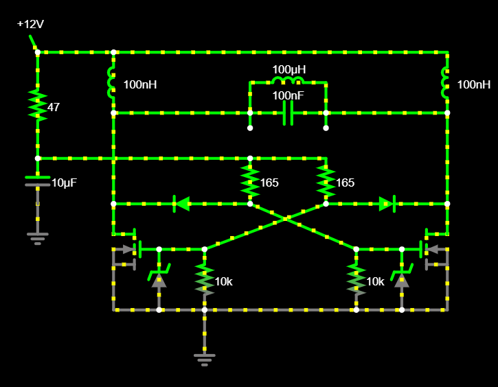
I've been playing around with a ZVS circuit on Falstad, and it seems that the voltage drop across the LC circuit is based almost entirely on the size of the 2 inductors outside of the tank (the voltage across the tank is 40 V when they are 200 uH and only 30 mV when they are 100 nH, there seems to be an exponential relationship. If someone could point me in the direciton of how to solve the equations for the inductors voltage drop that would be amazing. (Are the inductors creating a large EMF due to the quickly changing current from the LC circuit and hence the larger they are the bigger the EMF?)

Circuit with small incuctors

However the purpose of these inductors is to protect the powersupply from any feedback from the LC tank, however I am struggling to find how to calculate what size the inductors need to be to provide that protection.

\$\endgroup\$

2 Answers 2

0
\$\begingroup\$

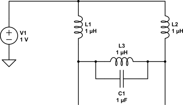
You have a pi network of inductors.

schematic

simulate this circuit – Schematic created using CircuitLab

That is, the three elements (well, not in this orientation but when flipped so L3 is above the line) look like the character Π.

With respect to the oscillator (C1, and the other stuff not shown), L1+L2 looks in parallel with L3.

Note that the circuit is regenerative: the cross-connected transistor pair has effective negative resistance, somewhere around -1/gm I suppose. The voltage reading isn't very meaningful because it will be divergent, either towards zero (insufficient gain for the load impedance) or maximum (increasing amplitude until the nonlinearity of the circuit takes over, and efficient operation ensues).

Normally we would design such a circuit so that L3 dominates, i.e. L1 and L2 are much larger in value. We would also design it so that, at the desired output power, the resonant impedance is a modest fraction of it. That is, if the supply were 20V and desired load current 10A, that's ballpark a 20V / 10A = 2Ω load, and to get a Q factor of 3 we would need \$Z_0 = \frac{2\Omega}{3} = \sqrt{\frac{L}{C}}\$. (The product LC is set by the desired operating frequency, and then all values are determined.)

\$\endgroup\$
0
\$\begingroup\$

Probably best way (at least for me) to understand the LC tank voltage swing is to think from energy point of view.
The inductor energy is E = 0.5 . L . I^2
From this relation you clearly see the energy of inductor rises extremely with increased current (square).
Now, when you consider another relation for inductor current:
U = L . di/dt (U is 12V)
you see for constant time the current rises more with lower L.

Now, putting all together for 100nH inductors:
Lower L = Higher inductor current = more energy stored in 100nH inductors
(Note: The 100nH coils are charged "hard" with direct connect to Vcc=12V during transistor On)

To be clear, more energy in 100nH inductors = more energy is transferred to LC tank = higher LC tank voltage.
(Note2: There is also an important relation between L/C ratio of tank and tank voltage swing, but that is for another time)

\$\endgroup\$

Your Answer

By clicking “Post Your Answer”, you agree to our terms of service and acknowledge you have read our privacy policy.

Not the answer you're looking for? Browse other questions tagged or ask your own question.