1
\$\begingroup\$

I'm working on a design to test/qualify vintage AT power supplies. I want to test all (+5v, +12v, -5v, -12v) rails. I want to be able to measure from -20% to +10%. I've got a DAC (built into my microcontroller for now) which can measure from 0v to 3.3v. To build in safety margins I want the outputs to be +/- 10% from that or 0.3v to 3.0v.

I'm intentionally stretching my skills a bit: they're strong with digital circuits but less so in analog. I believe I should be able to use an op amp here, and a quad op amp chip will match the four rails I want nicely. The primary reference I'm using is "Op Amp Gain and Offset Page" which can mostly automatically suggest the exact circuits I need to set up, and the resistor values to use. For three rails, this has worked great! I've even (LTSpice simulated and) breadboarded the results and with only minor tweaks I get exactly what I'm hoping for.

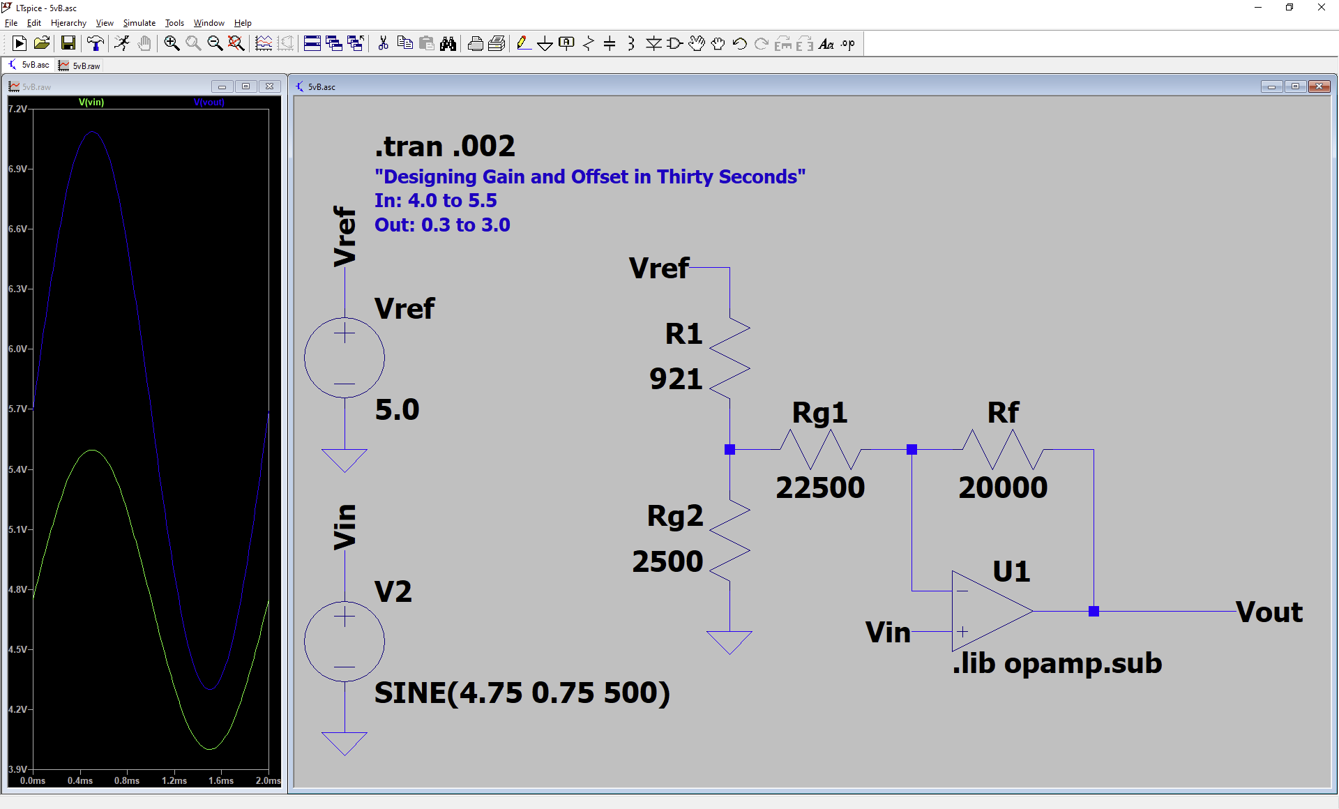
Except with the +5v rail. For that, it suggests case 2 and the case 2 page is broken. If I download and fix it, I get completely broken results (all solutions have huge errors -- maybe I didn't fix it perfectly?). If I instead use Designing Gain and Offset in Thirty Seconds I get the same m and b, and a resistor network. That's (I'm using a +5v reference, though I could be flexible a bit there if it helps)

"30 second" solution, simulated

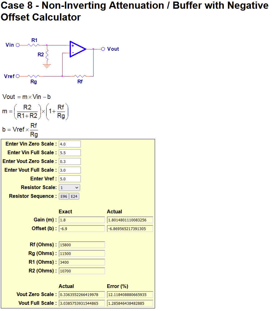
completely wrong, per simulation? Output is way too high, above the input rather than below. (This is probably a hint that I'm "doing something wrong", but I don't know what.) Somehow I figured out that "case 8" from the earlier-linked page seems to work, so I tried that and it gives:

"case 8" solution

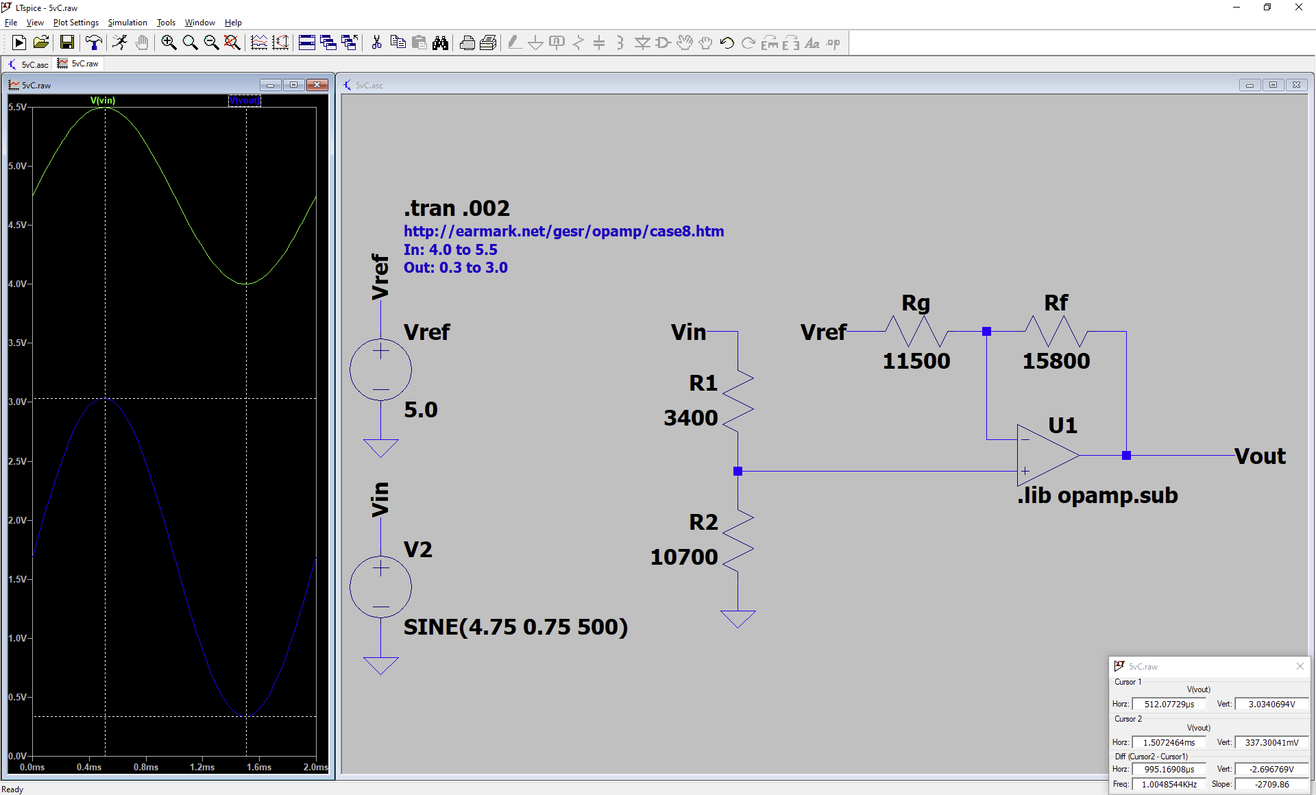
An acceptable-looking solution. And the simulation

"case 8" simulated

matches perfectly. But when I breadboard it (edit: with GND at 0v and V+ at 12v) an input at about 4.2v produces about 0.7v output and lower inputs never produce a lower output. I'm using potentiometers for my resistors, and a DIP LM324N quad-op-amp. These same components have worked great, producing the expected output range, for my other three input ranges (and their matching appropriate circuits).

Am I running into a real-world op amp limitation that the simulation does not cover? On a hunch, I repeated the "case 8" solution with an output range from 1.0 to 3.0v -- that works as expected on the breadboard, and seems to be a workaround I could select. But I'd like to use the full output range down to 0.3v.

\$\endgroup\$
2
  • \$\begingroup\$ My only question is why do you think you need op-amps for this? \$\endgroup\$
    – Justme
    Commented Jul 7, 2023 at 15:01
  • \$\begingroup\$ I want to both scale and offset four different voltages (and invert two of them). Happy to hear different solutions. \$\endgroup\$
    – arantius
    Commented Jul 8, 2023 at 20:56

2 Answers 2

4
\$\begingroup\$

The LM324 cannot sink current greater than (typically) about 50uA without some substantial output voltage (approaching a diode drop) and your topology requires it to do so. It would have to sink Vref/(Rf+Rg) to get the output to zero.

You can make the LM324 outputs range from 1V to 3V and it should work with a 5V supply.

\$\endgroup\$
1
  • \$\begingroup\$ This does seem to be the underlying issue. Larger Rf and Rg make things behave the way I'm hoping for. \$\endgroup\$
    – arantius
    Commented Jul 8, 2023 at 21:21
3
\$\begingroup\$

Am I running into a real-world op amp limitation that the simulation does not cover?

The op-amp you chose probably needs to have a small negative rail so that the output can adequately reach 0 volts.

Even so-called rail-to-rail op-amps struggle to get closer than a few tens of milli volts and, regular op-amp outputs usually can't get within a volt of the power rails.

You also need to ensure that the input voltage range is within the power supply range of the op-amp and, in particularly, for the LM324, it's output limits at around 3.5 volts on a 5 volt positive supply.

\$\endgroup\$
2
  • \$\begingroup\$ I targeted 0.3v as the low end output partially to avoid trying to drive all the way to the zero volt V- input. But moreover, as I said, I'm getting the expected 0.3 to 3.0 volt output, for other input ranges (and resistor networks). I'll edit in my V- and V+. \$\endgroup\$
    – arantius
    Commented Jul 8, 2023 at 20:56
  • \$\begingroup\$ Please don't edit in amendments that make my answer look like I didn't read your question properly. \$\endgroup\$
    – Andy aka
    Commented Jul 8, 2023 at 22:54

Your Answer

By clicking “Post Your Answer”, you agree to our terms of service and acknowledge you have read our privacy policy.

Not the answer you're looking for? Browse other questions tagged or ask your own question.