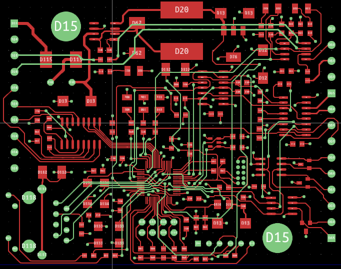
I have a PCB, which was not designed by me. The Ethernet works intermittently between multiple copies, except for on one, where it works just fine.
I want to start troubleshooting at layer 1, and when I looked at the design for this PCB, I noticed that there is no impedance control, or length matching on the traces going from the RJ45 to the PHY (which is integrated into the microcontroller). These traces are routed like GPIO, not like a differential pair. There is also no ground plane on this board, so calculating the actual impedance if the traces is going to be very difficult.
I suspect there is a signal integrity issue that is causing the ethernet to work intermittently, but how do I go about proving it? I was thinking of using my VNA and measuring the traces individually (single ended), but I was hoping to get some different ideas from this post.
The ethernet jack in question: Mouser Link
So, I did end up hooking my VNA up to the boards, and here is the results I got. Note this was on raw boards, no RJ45 or MCU attached. Measured at 66MHz.
| Line | Resistance | Reactance | SWR | Smith Chart | Delay | Complex |
|---|---|---|---|---|---|---|
| TX+ | 16.1Ω | -64.2Ω | 7.2 | 16.0Ω 37.2pF | 4.0ns | .21-j.75 |
| TX- | 18.3Ω | -64.2Ω | 8.5 | 18.3Ω 38.4pF | 4.2ns | .19-j.76 |
| RX+ | 16.5Ω | -62.0Ω | 7.7 | 16.5Ω 39.2pF | 4.0ns | .19-j.75 |
| RX- | 15.8Ω | -64.0Ω | 8.5 | 15.7Ω 37.5pF | 4.0ns | .20-j.75 |


