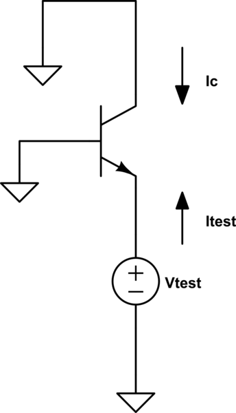
When computing the input resistance of this common base configuration, the collector current \$I_C\$ is approximated as equal to the emitter current \$I_E\$:

simulate this circuit – Schematic created using CircuitLab
It is \$I_C = g_m V_{BE} = g_m(-V_{test}) = -g_m V_{test} = -I_{test}\$ and therefore
$$R_{in} = \frac{V_{test}}{I_{test}} = \frac{V_{test}}{g_m V_{test}} = \frac{1}{g_m} $$
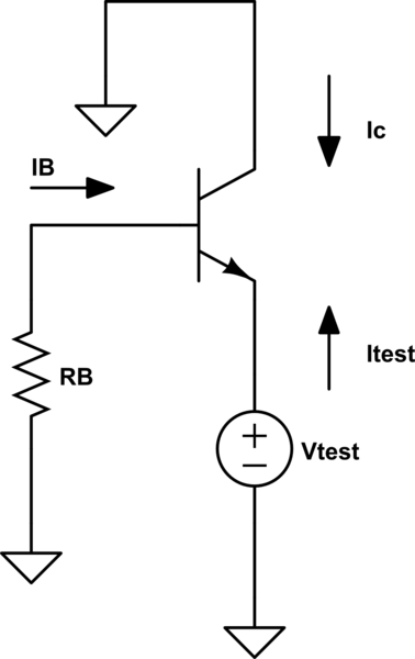
But when a base resistor is added, the approximation \$I_C \simeq I_E\$ is no more used:

Now instead the computation is more complex:
$$ I_C = g_m V_{BE} = g_m(V_B - V_E) = g_m \left( -R_B I_B - V_{test} \right) $$
$$ I_{test} = - I_E = - (I_C + I_B) = - \beta I_B - I_B = - \left(\beta + 1 \right)I_B $$
$$ I_C = g_m \frac{R_B I_{test}}{\beta + 1} - g_m V_{test} $$
$$ I_{test} = -I_C - \frac{I_C}{\beta} = -\left( I_C + \frac{I_C}{\beta} \right) = -I_C \left( 1 + \frac{1}{\beta} \right) $$
$$ I_C = -I_{test} \frac{\beta}{\beta + 1} $$
$$-I_{test} \frac{\beta}{\beta + 1} = g_m \frac{R_B I_{test}}{\beta + 1} - g_m V_{test} $$
$$I_{test} \left( g_m \frac{R_B}{\beta + 1} + \frac{\beta}{\beta + 1} \right) = g_m V_{test} $$
$$ R_{in} = \frac{V_{test}}{I_{test}} = \frac{\frac{g_m R_B + \beta}{\beta + 1}}{g_m} = \frac{R_B}{\beta + 1} + \frac{\beta}{g_m(\beta + 1)} $$
Why here (and only here) the results are radically changed if \$I_C \simeq I_E\$?
