As you've stated, your case isn't metal, so there is nothing to 'chassis ground' to.
On the other hand, your board assumes a chassis ground (actually, it doesn't, we'll get into that below.) The assumption for this depends on the designer's intent, but most often it is meant to form a low-impedance common ground for external connections. Why? To help deal with disturbances such as static discharge and common-mode noise invading the I/O connectors.
My suggestion? If your design needs a chassis ground for some other reason, provide an internal metal plate that ties your I/O panel and board ground together. Make the I/O panel such that it picks up any shield grounds on your I/O. This will greatly improve your system EMI and ESD performance without the full metal enclosure.
If you have an internal power supply, this will have a ground that wants to connect to chassis ground:
- DC supply: tie (-) input to the plate
- AC supply (2-wire): tie Y-cap ground point to the plate
- AC supply (3-wire): tie earth to the plate
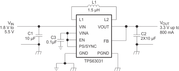
Now, a word about the regulator. The schematic is misleading. The TPS regulator doesn't require a chassis ground. It does however require a thick, low-impedance power ground for the high-current AC paths. This is distinguished from signal ground which is for the control and feedback components.
Their schematic used the following symbols:
- 'chassis' (three slanted lines) for power ground. This is misleading.
- 'common' (three horizontal lines) for signal ground.
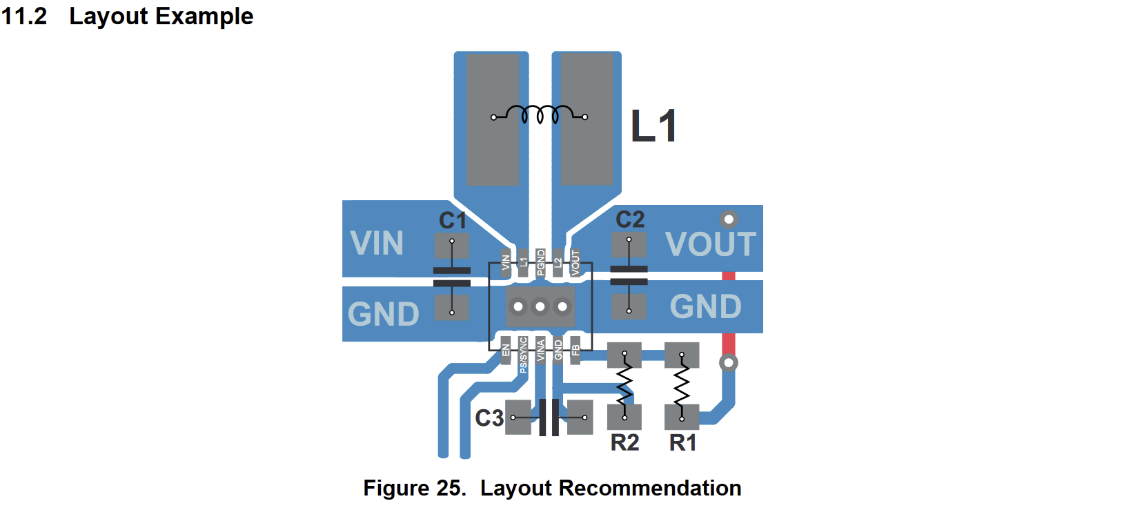
At any rate, the two grounds should be star-tied near the device. The datasheet has a layout example that makes this clear:

from https://www.ti.com/lit/ds/symlink/tps63030.pdf
That fat 'GND' area is the low-impedance PGND path, drawn misleadingly as 'chassis' in the schematic. It connects to pin 3, PGND, the thermal pad (also PGND) and finally to pin 9, GND, and then on to C3 and R2. The thermal pad is the 'star tie' point that connects PGND and GND.
Notice that the input and output caps tie to PGND. This isolates their dynamic switching currents to a small, low-impedance loop. This isolation is key for switching regulator performance and low-noise operation.
tl; dr: follow their layout recommendation.


