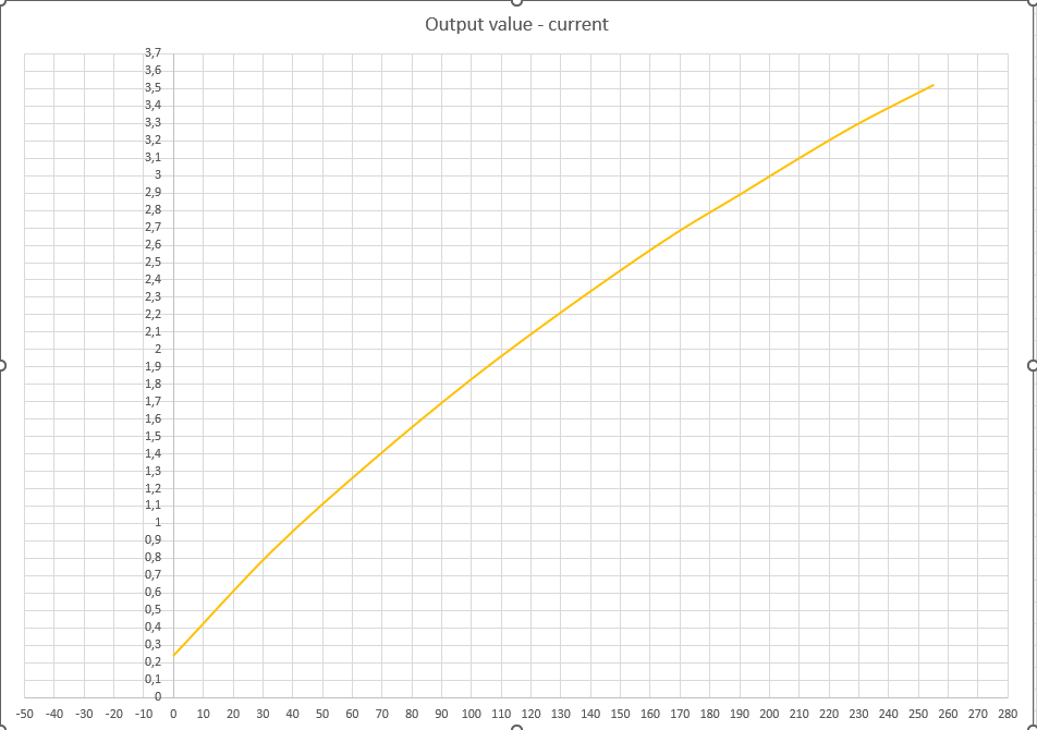
I have a box of water, which temperature I have to regulate to a ramping setpoint which could go both below and above the ambient temperature. So I have decided to use a Peltier for both cooling and heating. The Peltier is driven by a regulated current source (DC-DC buck convertor), but there is a catch - it cannot go under 0.5A. Reversing of polarity is done by relay. The convertor can be switched on/off by an enable pin.
I have decided to try to use PID to control it and more specifically the PID_V2 library for arduino by Brett Beauregard.
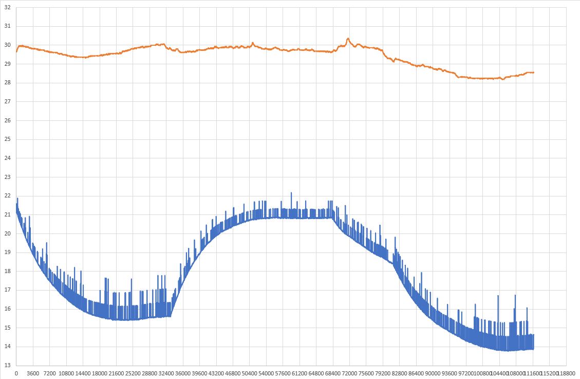
I did an open loop manual step test in cooling direction in order to have general idea of the system and I got this:

The step in the beginning is done by increasing the current from 1.284A to 2.258A. The temperature drops from 21.13 to 15.4 degrees, but since the outside temp has dropped by a half a degree, we can say that the drop is about 5C degrees. So dI/dT = 0.974/5 = 0.195 A/degree. Time constant seems to me like around 135 minutes. I haven't done step test with heating, because I don't want to go to high temperatures.
I know, that Peltier direction should not be reversed when there is already temperature gradient over it, so first thing that I want to make sure is that reversing polarity happens only when the Peltier is passing through zero and this is happening slow enough. So: 1 - how can I incorporate this condition in the PID control?
2 - the gap below 0.5A. Since I cannot control the current there, there are two or three possible solutions, but I don't know which will be better. First one is to just push the minimum current in the direction that I want to go. Second one is to switch to ON/OFF cycle, which at low current won't be a problem and third one - to vary the fan speed of the peltier coolers, which will affect their cold side/hot side temperature difference. I don't know how to incorporate those without confusing the PID.
3 probably biggest problem is reversing the Peltier. The transferred heat from the cold side to the hot side is more or less proportional to the current, but in the opossite direction we have to add to this the Jaul heat which is proportional to the square of the current. I assume for this I will need to switch PID coefficients and probably do some kind of calculation of the actual command to the DC-DC in order to get linear current change to a linear change of PID output. Any ideas on this one?
4 I found that Brett Beauregard PID library has a functionality that he calls "Proportional on measurement", which according to his blog article prevents overshoots on setpoint step, which I will do all the time. I want to try it, but I don't know how to calculate Kp for my system.
5 Will the direction switching confuse the PID (probably the integral part) somehow? With what Ki and Kd should I start?
For now, these are the questions that are bothering me.


