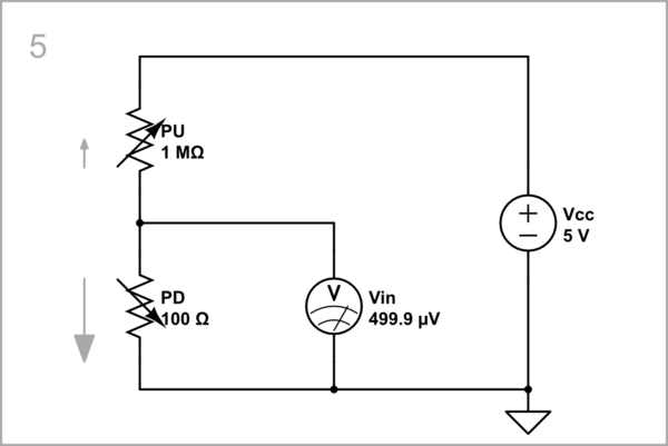
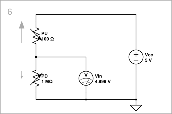
When the microcontroller pin is configured as an input, it is effectively electrically disconnected from everything else. That's what we mean by high impedance - the resistance between the pin and anything inside the MCU is very, very high. If you don't connect that pin to something externally, then it's effectively electrically disconnected from everything.
This doesn't mean it isn't being "monitored", the MCU is still measuring to determine if its potential is high or low, so that software can "read" its value, but being physically unconnected, its potential (voltage) is free to rise and fall under the influence of noise and nearby changing potentials. Thus it's liable to flap wildly up and down in potential, seemingly randomly, and this will produce unnecessary switching currents inside the MCU.
Can I directly connect GPIO input pin to high level logic like for example 5V with[out] using any resistor?
Unused inputs can be tied directly to 0V or +3.3V or +5V (depending on the MCU) to prevent the input from freely changing potential, and to avoid unnecessary switching currents.
You could achieve the same effect with a resistor to +3.3V or ground, but a wire is cheaper. Obviously, connecting the pin directly to +3.3V or ground means you can no longer use that pin as either input or output, since its potential is now fixed.
You didn't ask, but unused inputs can be prevented from fluctuating randomly in potential by configuring them as outputs instead.
Why do we use pull-up resistors on the input pins of a microcontroller?
Alternatively, to keep an unused input "quiet", you can tie it to either supply with a resistor, which will work to more gently coerce the pin's potential high or low. If the MCU has this feature, you could configure the pin to use the MCU's own internal pull-up or pull-down resistor.
If you intend to actually use the input, by applying a potential and having the MCU interpret that as a digital high or low, then using a pull-up or pull-down resistor doesn't prevent you from explicitly applying your own high or low potential, from another voltage source, as long as the resistor's "coersion" is far weaker than the source of signal trying to override it.
If you don't intend to use the input today, perhaps you will in the future. Maybe you'd would use a pull-up resistor to quieten an unused input today, but in later or different circuit revisions you could simply not populate that resistor, leaving it free for use.
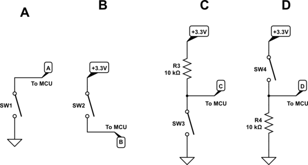
While all the above is true, as I said, it's probably far easier and cheaper to just tie an unused input directly to a supply rail with a wire, so there must be another reason why we use pull-up and pull-down resistors. To explain why, first you must understand the electronics of components connected in series between supply rails. I wrote another answer about this, which you can read here for more details. In the meantime, I'll refer to these circuits:
simulate this circuit – Schematic created using CircuitLab
In circuit A, node A (which is feeding an MCU input), when switch SW1 is open node A is floating, and since the MCU input is high impedance, it can fluctuate in potential. In other words, the potential at A is undefined. It is only when the switch is closed that the potential at A becomes forced to 0V, because there's now a very low resistance between A and 0V. You can, in a sense, consider the switch to be "pulling down" the potential at A.
The same problem occurs with circuit B, but this time the switch is only able to pull node B high; otherwise the potential at B is undefined, and subject to noise and interference.
Without a pull-up (or down) resistor, when the switch is open, MCU input potential is not being explicitly controlled, and is ambiguous. The MCU would have no reliable way of distinguishing between switch states. We would use a resistor to avoid this condition when the switches are open, which I show in circuits C and D.
For circuit C we are coercing node C high with R3, providing a gentle "pull" towards +3.3V. With the switch open, because that "pull" experiences no opposition, the potential at node C is 3.3V. However, by closing switch SW3, there's suddenly a much more forceful, low impedance tug towards 0V, far stronger than the pull up, so the voltage at C falls very close to 0V. How close depends on the resistance of the switch when its closed. As long as we choose a pull-up resistor R3 far greater than the resistance of switch SW3 when closed, the switch will be able to easily overcome any opposition from R3.
Circuit D shows the same principle using pull-down resistor R4 to gently set node D at 0V, unless switch SW4 is closed, which forcefully pulls D high.
In a moment I will address the "current limiting" benefits of R3 and R4, but for now, let me illustrate another incredibly useful benefit for pull-up resistors (and I suppose pull-down, but that's not seen so often). Consider these circuits:
simulate this circuit
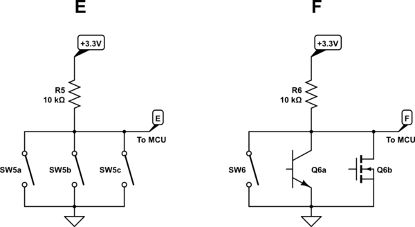
On the left (E) I illustrate how two or more switches can be connected in parallel, such that pressing any one of them will pull the output node E low. The exciting part is that we may use any type of switching element in the place of the those mechanical devices, such as transistors, which fulfill the same role.
I've done that in circuit F. The advantage here is that those transistors can be switched electronically, by the output from some prior stage, and by combining them in parallel like this, you can have any one of them "activate" some MCU function.
This technique is called "wire-NOR" (or often just "wire-OR") since switching any transistor on (which requires a "high" base/gate potential), or activating any switch, will cause the output F to go low.
Many devices such as sensors, comparators, logic gates and I2C bus participants use transistors in this "open-collector" or "open-drain" configuration, where the collector/drain of the transistor (the output) is not actually connected to anything inside the IC, leaving you free to join many collectors/drains together. With a single external pull-up resistor, you can have any of the devices pull their common output low. See the LM393 comparator and the 74HC03 logic IC.
If pull-up resistor is used to limit the current, the GPIO input pin will anyways have a very high input impedance. Then why do we need a pull-up resistor?
There's no need to limit current if you are connecting an unused input high or low, since as you point out, the high impedance of that input will draw almost no current. That's why you don't need to use a resistor in that particular role, and can employ a direct link instead.
However, in all the circuit scenarios I illustrated above, a resistor is mandatory. Imagine what would happen if we replaced any of the resistors above with a direct link to the supply rail. When the switching element closes, this would create a direct short circuit across the supply, causing unconstrained current flow, and something would break.
How to calculate the value of a pull-up resistor? Why generally 10k ohm resistor is used?
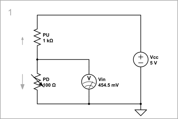
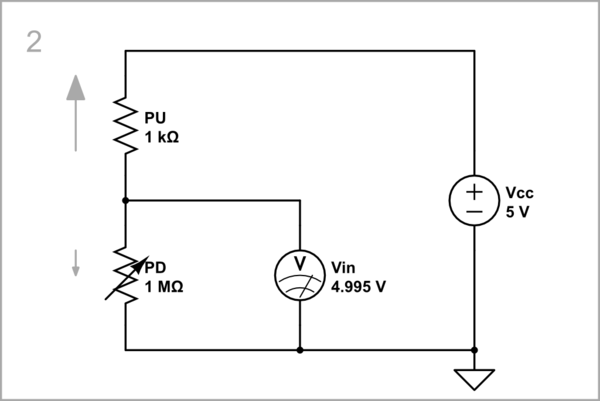
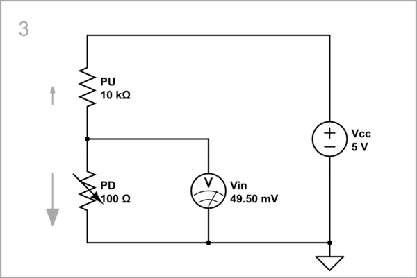
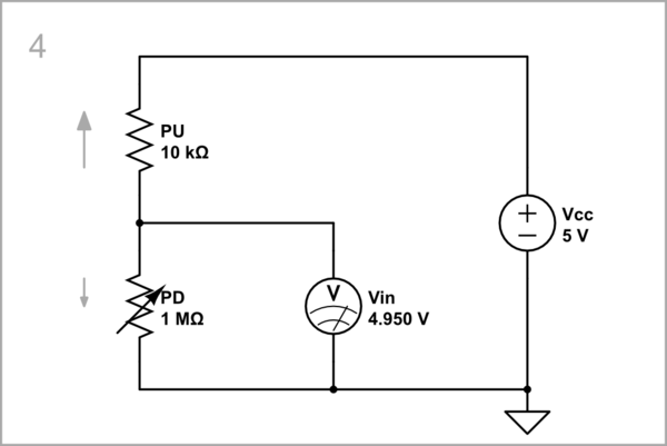
Low resistances correspond to higher currents. Higher currents correspond to higher power dissipation and consumption. For battery powered equipment this is critical. For mains powered systems, not so much. Given that we are typically dealing with a few volts, and the currents we can use without burning things up or being so small that the signal is swamped by noise and interference, range between microamps and milliamps, and we most often find ourselves using resistances in the 1kΩ to 1MΩ range.
What you settle on yourself is entirely dependent on the application, its power constraints, and any noise sources present. Using a 1kΩ pull-up resistor for a switch in a system being powered by a coin cell would be silly; you'd be better off closer to 1M. On the other hand, using open-collector PLC sensors in an industrial setting, with electrical noise everywhere, but oodles of current at your disposal, kilohms are much more sensible.
For a typical home project with a switch and a pull-up resistor, anywhere from 10kΩ to 100kΩ might be perfectly fine, a compromise between power consumption and noise immunity.
Update: When don't we need a pull-up/down resistor?
If the device providing the MCU input signal is already able to both pull-up and pull-down itself, which we refer to as an output that can both sink and source current, then you don't need a resistor. In fact, putting a resistor where one is not needed is usually detrimental to performance in some way.
I illustrated open-collector/drain configurations above, which do require a pull-up resistor, but the great majority of logic devices available today have what we call "push-pull" outputs, or already have built-in pull-up/down resistors when required.
For example, the 74HC00 IC, which contains four NAND gates in a single package, each output having two transistors, one that "pulls" down, like Q6b above, and another that pulls up to the positive supply, replacing R6 above. Contrast this with the open-drain alternative, the 74HC03, which I referred to above, and which contains only the lower "pull-down" output transistor. The 74HC00 outputs can directly drive an MCU input with no resistor necessary to pull anywhere, but the 74HC03 will need one, or some other means of "pulling up".
Many digital sensor devices have open-collector/drain outputs, which would require a pull-up resistor, the value of which can only be determined from consulting their datasheets. The only useful information comes from datasheets, so I would encourage you to get used to reading them, and paying careful attention to what you can/must or cannot/must-not connect to their outputs.
It might help you to swap your question around; instead of asking when does my MCU input require a pull-up/down resistor, perhaps it's better to ask when the source of the signal fed to the MCU needs to be pulled up or down. In other words, if the source is thin air (the MCU input is "floating"), it's the source that needs help being a one or a zero, with a resistor to one or the other supply rails.


