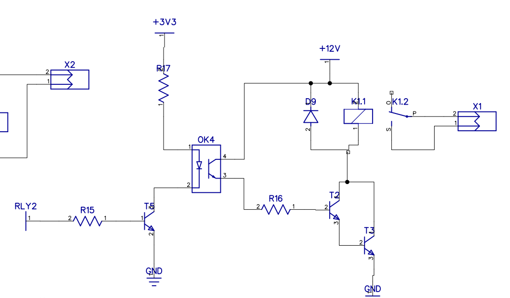
I have an embedded device which uses an STM32 microcontroller to drive a relay. If the controller leaves the relay turned ON for a long time (~ 1 hour), the relay then refuses to turn back off when it receives the signal to do so.
- I checked the voltage at the GPIO output (pin 1 of R15) and the controller successfully changes the pin state when it should.
- I get 0.7V across pin 1 of T2 and GND when the relay is ON, and close to 10V when it's supposed to be OFF but remains ON.
- I get 1.4V across pin 1 of R16 and GND when the relay is ON. When the relay remains ON after the controller turns it OFF, and I connect a multimeter across pin 1 to check the voltage, the relay immediately turns OFF.
Some more info:
- Reports from the field suggest that this issue has popped up only in a few controllers (a batch possibly) but that isn't guaranteed to be the case. The relays were all from the some batch.
- This device is on a PCB and there's a transformer sitting right next to the relay which heats up to a small degree after long hours of operation.
- Turning the system OFF, and providing external 12V to the relay coil terminals turn the relay on and off promptly
- Unlike shown in the diagram, the grounds on both sides of the optocoupler aren't shorted together.
Are there any design issues with the circuit itself? Being a newbie I can't spot anything that is wrong with the design of the circuit itself. Any help is appreciated!
Edit: Component values
R15 - 470E
T4, T3, T2 - BC547
OK3 - PC817
R16 - 2K7
D5 - 1N4007
K1 - HF118F

