I am trying to measure mechanical deformations using a full Wheatstone Bridge. In order to do that, I connected the bridge to an instrumental amplifier (INA125PA).
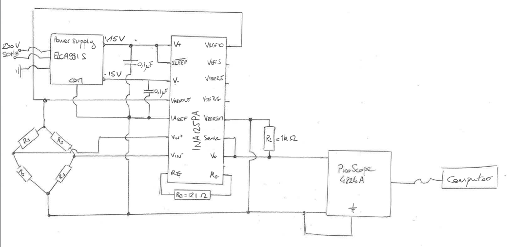
The amplifier is powered with a dual supply of +-15 V, provided using a symmetric power supply (ELC AL991S). The Wheatstone bridge (350 Ohm gauges) is supplied at 10V using the reference output voltage provided via the amplifier. The following schematic represent the whole electronic circuit.
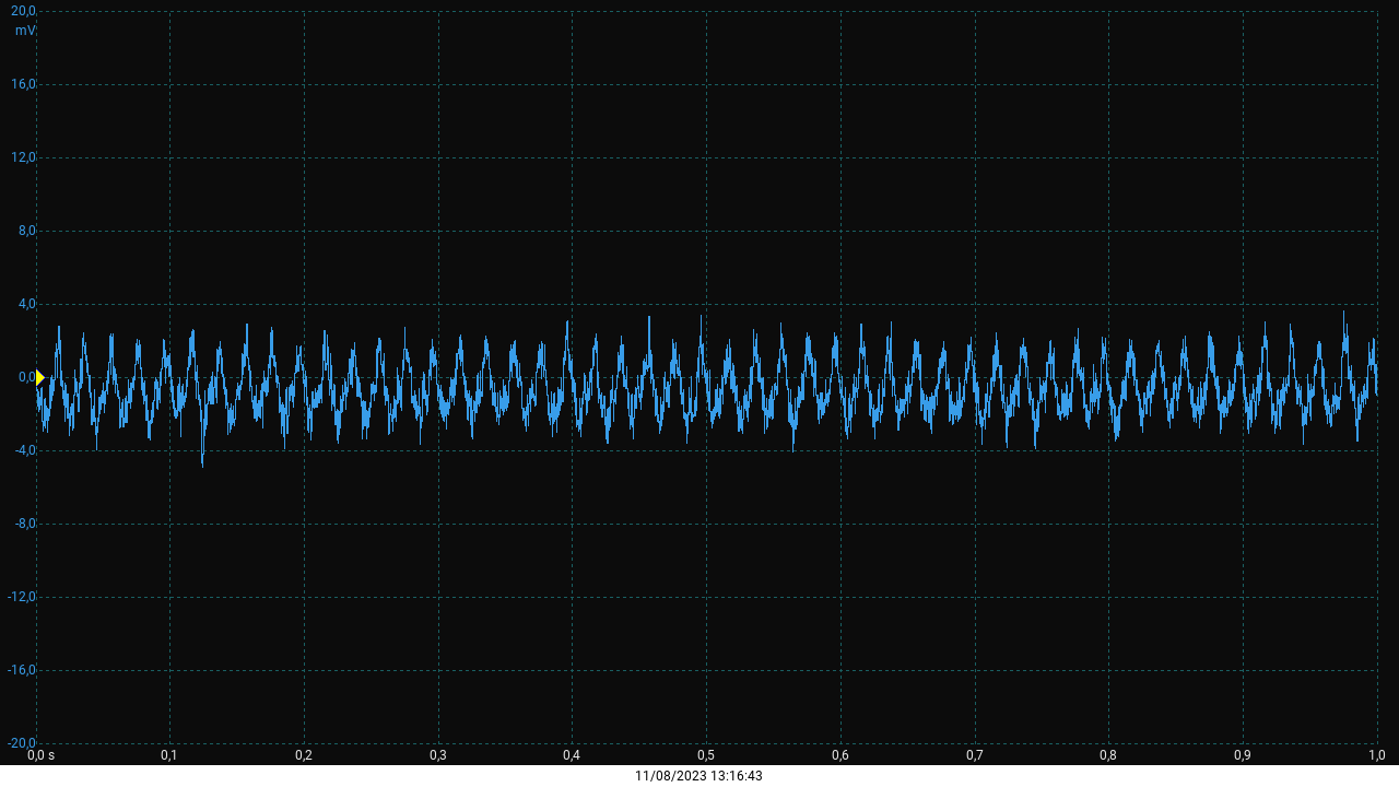
However, one the amplifier is turned on, there is a 50 Hz noise of around 4 mV of amplitude, which interferes with the measured signal (a reflecting deformation wave of low frequency). The measurement was done using a Picoscope 4824A (Documentation)

I wish to get rid of this noise. I suspect a problem of ground connection, creating a loop eventually, but I lack the knowledge to identify it.
Do you have any lead I could follow?
Edit:
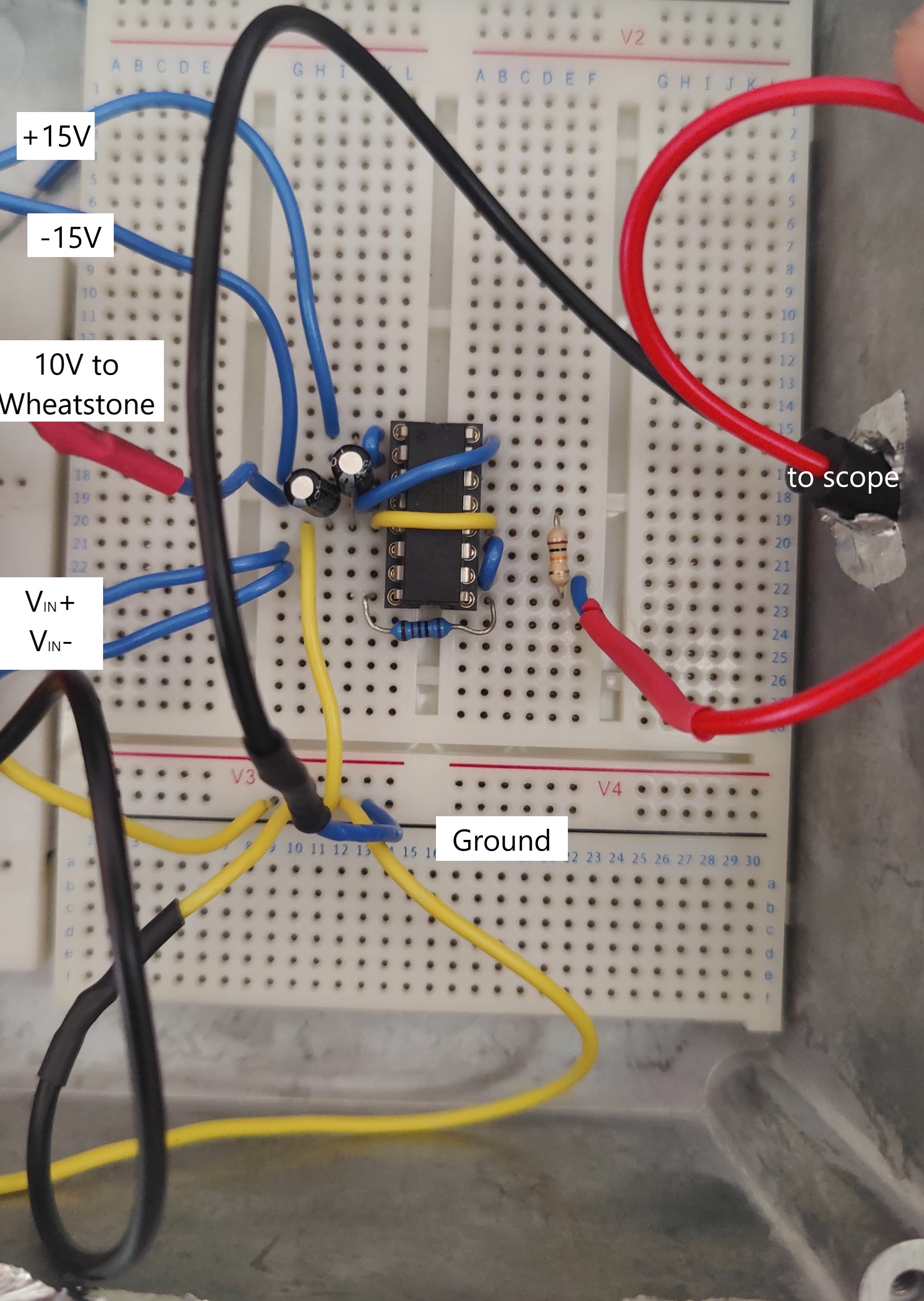
I've been asked to provide a picture of the circuit layout. Here it goes:
 I am curently using a Breadboard, which was usefull for the time being due to the flexibility it offers. I plan on soldering everything.
I can confirm that the scope is not aliasing.
The wheatstone bridge is wired using same length wires soldered to the strain gauges. Regarding the connections in between the different elements, I use either BNC cables or banana plugs (for the power supply) (not visible on the previous picture)

