4
\$\begingroup\$

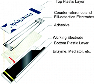
We are experimenting with a glucose test strip (below) in our chemistry lab using an electrochemical method where a potential is applied (150 mV) across the working and reference electrodes and the resulting current is measured across the working and counter electrodes.

enter image description here

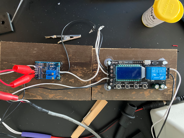
We have found that sampling time is critical, so we set up a sample detection relay system using the test strip’s fill-detection electrode. When the sample reaches the electrodes, we detect very low mV across the fill-detection and reference electrodes that the relay itself cannot directly detect.

This setup amplifies the output (the two red leads) from the fill detection/reference electrodes (from mV to V) and that signal hits the relay, which triggers the instrument to start collecting data. The electronics triggering setup is working great. The problem we are running into is a tremendous amount of background noise.

enter image description here

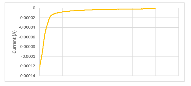
This is the signal without the relay system connected (manual start is used):

enter image description here

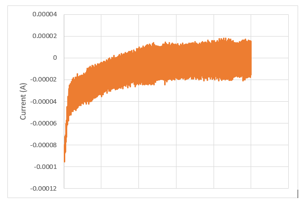
When the relay system attached:

enter image description here

We can use the instrument’s software to get this smoothed response, but even so it does not compare to the very smooth and more precise signals we get when the relay system is not connected.

enter image description here

Is there anything we can try, electronics circuit-wise, to reduce this noise?

\$\endgroup\$
2
  • 1
    \$\begingroup\$ what does that signal hits the relay mean? ... please add a circuit diagram to your post ... use the schematic editor that is available when you edit your question ... click save and insert when you complete drawing the circuit diagram \$\endgroup\$
    – jsotola
    Commented Aug 23, 2023 at 16:10
  • 2
    \$\begingroup\$ You are dealing with picoamps with things dressed out as I see in the picture? Just want to be sure I'm reading the y-axis correctly. \$\endgroup\$ Commented Aug 23, 2023 at 16:46

2 Answers 2

6
\$\begingroup\$

Nothing in your added circuitry produces much noise. There is an MCU in the timer which may produce a bit of noise, but at very high frequency and easily filtered (and, if I am correctly about your amplifier, it will barely respond to such frequencies even without filtering).

Rather, the noise is suggestive of a switching power supply being used to power the modules which is the root cause. I suggest swapping the supply or supplies out for batteries to narrow down the problem. It's possible that better grounding will help with the existing supply or supplies. Could just be mains noise too, which an oscilloscope would help with diagnosing.

\$\endgroup\$
3
\$\begingroup\$

It would be good to get a scope trace of the signal/noise, in particular to see whether it is mains hum.

Without a schematic it is hard to be definitive, but I wonder if you are either introducing an earth loop through multiple return paths, or simply coupling noise directly through separated + & - supply lines to and from the relay.

From the photo it seems both might be an issue.

I would definitely start by twisting together the black and white supply wires to reduce the loop coupling area.

I would also try an avoid any loops involving the PSU and ground of the signal you are trying to measure. One common option is to use differential sensing of the signal you are trying to measure, to remove common mode noise.

It might also be that you have a noisy PSU, and the fill sense circuit is coupling this back into your signal circuit. Perhaps see if you get the noise with the relay in circuit, but the red wires disconnected. If this is the issues, adding common-mode ferrites on the red sense wires might help. as might twisting them together.

\$\endgroup\$

Your Answer

By clicking “Post Your Answer”, you agree to our terms of service and acknowledge you have read our privacy policy.

Not the answer you're looking for? Browse other questions tagged or ask your own question.