What is the role of the input coupling capacitor?
OP has neglected the input coupling capacitor (not shown in their schematic; let's tentatively call it C1). So it would be good to clarify what its role is here. There are several textbook approaches to this, the worst being that "the capacitor had a high resistance for DC and a small resistance for AC", that "the capacitor did not pass DC but AC", and that "the capacitor galvanically isolated the input source from the bias circuit". They are generally correct but do not explain exactly what is going on in the input circuit. A good intuitive explanation is needed for capacitor behavior in the time domain rather than the frequency domain.
Basic idea
The input capacitor can be thought of as a "rechargeable battery" which is kept charged up to the bias voltage and its voltage is added to the input voltage in series (according to KVL). Thus two voltage sources, one (Vin + Vc) perfect and the other (Vcc-R1-R2) imperfect, are connected in parallel so the former overrides the latter. Their DC voltages are the same so the input AC voltage is superimposed on them and appears at the output.
Building and exploring
Bias circuit: Let's assume that the next transistor stage (represented by the voltmeter Vout) requires a 5 V bias voltage. We can get it from Vcc through a voltage divider R1-R2. Since the idea here is that the input voltage can directly change (in parallel) the divider's output voltage, the voltage divider must have a relatively high output resistance. Figuratively speaking, this is an "intentionally degraded voltage source" (with an artificially increased output resistance).
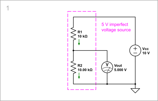
simulate this circuit – Schematic created using CircuitLab
Connecting equivalent voltage source in parallel: What will happen if we connect a perfect voltage source with the same voltage (5 V) in parallel to the output of the voltage divider? Nothing... Because there is no voltage difference, no current flows and the output voltage does not change (by the way, this arrangement is known as "bootstrapping"). The interesting thing about this "DC current-blocking technique" is that it does it through a reverse equivalent voltage and not through an infinitely high resistance (open circuit).

simulate this circuit
Inserting an input voltage source in series: Nothing changes even if we insert an input voltage source Vin initially with zero voltage.

simulate this circuit
Vin > 0: Let's now "wiggle" Vin; for example, first increase it with 1 V. Since the two voltage sources (Vin and Vc) are connected in series, in the same direction, their voltages are summed and the total voltage (6 V) appears at the divider's output. Note that this composite voltage source Vin+Vc injects current through R2 that is added to the initial divider's current. Figuratively speaking, the composite input voltage source "pulls up" the divider's output.

simulate this circuit
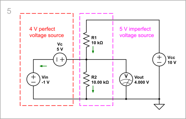
Vin < 0: Let's now decrease Vin with 1 V. As a result, the divider's output voltage becomes 4 V. Now the composite voltage source Vin+Vc "sucks" current from R1 that is subtracted from the initial divider's current. Figuratively speaking, the composite input voltage source "pulls down" the divider's output.
simulate this circuit
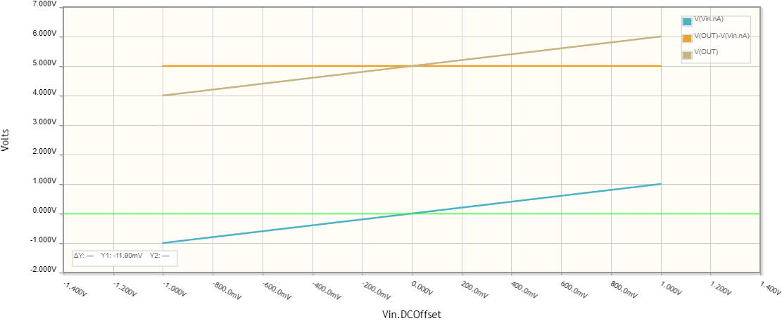
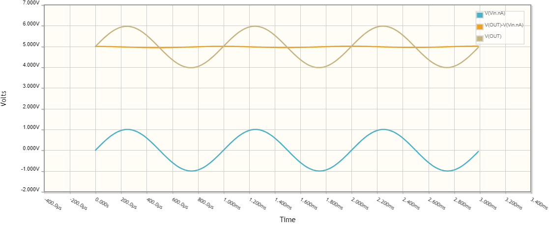
Of course, we can use the CircuitLab DC sweep simulation to see the process through time. As you can see, the input voltage is "lifted" with 5 V and appears at the output.
AC input voltage: So, in this way we can "move" (bias) the zero level of the AC input voltage from the ground to the divider's output.

simulate this circuit

Replacing the "battery" with capacitor: Now it remains only to replace the battery with the more convenient capacitor C. Even more interesting thing than above is that the capacitor blocks the DC current both through an open circuit (insulator) and a reverse equivalent voltage.

simulate this circuit
The operation of the circuit is exactly the same.
OP's mistake
... is the absence of a "voltage shifting" element (charged capacitor) between the input voltage source and the divider's output. As a result, the input voltage appears directly at the output without being "shifted".

simulate this circuit


You can see the continuation of this story about the output coupling capacitor C2 in my next answer.


