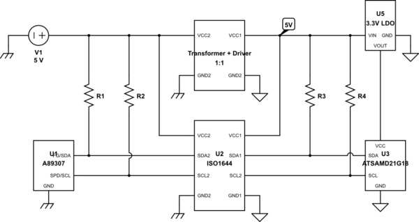
I'm working on a BLDC driver using Allegro's A89307 controlled by an isolated ATSAMD21G18 via TI's ISO1644 I2C digital isolator. The simplified I2C connection is shown below, I omitted all the bypass caps/other connections for clarity.

simulate this circuit – Schematic created using CircuitLab
(For pull-ups I'm currently using 1kΩ on side 2 and 2.2kΩ side 1, however I've tried numerous other values without any different behavior)
Device characteristics
According to all three's datasheet the logic low levels are all in spec amongst each other:
- A89307's logic low threshold is 800mV, ISO1644's side 2 has a logic low output of up to 400mV.
- A89307's logic low output is up to 300mV, ISO1644's side 2 has a logic low threshold of 2V.
- ATSAMD21G18's logic low threshold is 1V, ISO1644's side 1 has a logic low output of up to 710mV.
- ATSAMD21G18's logic low output is up to 400mV, ISO1644's side 1 has a logic low threshold of 480mV-560mV.
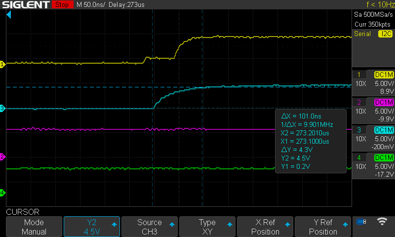
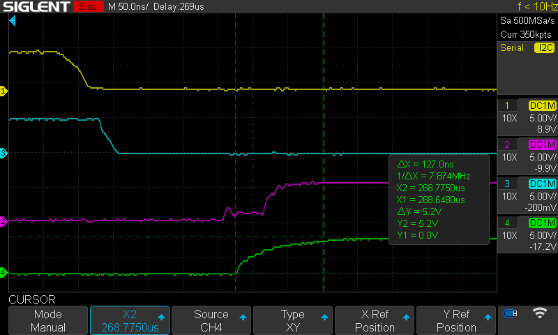
I've used my oscilloscope to check the signals. All voltages are as expected, and all the rise times are well within the I2C limits for Standard Mode.
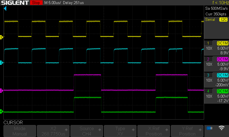
(Yellow=Side 1 SCL, Purple=Side 1 SDA, Blue=Side 2 SCL, Green=Side 2 SDA)
SCL rise times
SDA rise times
I lined up both sides of the isolator and its near perfectly aligned, there are no missed pulses for either side.
What's wrong?
I can't seem to get any possible form of consistent/usable response with any I2C command, and I'm also getting strange SCL clock speeds compared to what I'm setting it to.
I have to try dozens and dozens of times before the A89307 will even ACK's it's own address, let alone any other bytes I send. When it does complete a full read or write, it's response is almost always either seemingly random bytes, all 0x00s, or all 0xFFs. I'll read the same register address a dozen times in a row and get 3+ completely different responses back. Very very rarely I'll get the correct data back. When it finally responds to a write for a given (shadow) register it'll read it back and its always 0xFFFFFF.
Update: Clock randomness was due to the A89307's SCL pin getting smudged into the pin next to it from my scope probe tip. That whole mess is resolved, the chip is still unresponsive however.
What is the A89307 doing while I'm changing the clock speed? Most of the values I set it to result in the A89307 being 100% unresponsive, it will never ACK its address. A few seemingly random settings cause it to enter into the previously mentioned behavior of flakey responses with random data sent on reads. Some of these frequencies are well above the 100kHz max from the datasheet, e.g. it appears to be "functional" at 400kHz.
I wrote a simple program to test this where I start the I2C handlers with a specific clock speed, make a read request to the same register 4096 times, turn I2C off, report a summary, repeat with a different clock speed. The results from a handful of frequencies were (the clock frequency I actually observered on my scope jumped around between ~430kHz, ~230kHz, ~100kHz, ~10kHz):
clk=400000Hz successful_reads=33 failed_reads=4063
clk=100000Hz successful_reads=0 failed_reads=4096
clk=75000Hz successful_reads=33 failed_reads=4063
clk=64000Hz successful_reads=0 failed_reads=4096
clk=48000Hz successful_reads=0 failed_reads=4096
clk=25000Hz successful_reads=30 failed_reads=4066
clk=24000Hz successful_reads=0 failed_reads=4096
clk=12000Hz successful_reads=0 failed_reads=4096
clk=7000Hz successful_reads=0 failed_reads=4096
clk=6000Hz successful_reads=0 failed_reads=4096
What have I tried?
- Many any different pull-up resistors - 100Ω, 220Ω, 1kΩ, 2.2kΩ, 4.7kΩ, 10kΩ, 22kΩ, 47kΩ - with different combinations for side 1 and side 2 as well as same value across both.
- Added a bit of series resistance to dampen any cross-talk - 60Ω, 100Ω, 220Ω.
- Swapped the A89307 with a back-up one I also bought.
- Added wide range of delays between I2C commands, from 0 (consecutive) to 25ms.
- Tried with different microcontrollers - started with an ATTiny1627, swapped to an ATmega2650, then to the current ATSAMD21G18.
- Tried different I2C implementations - ArduinoCore-samd Wire, then I2C_DMAC.
- Prior to starting the I2C handlers, reading SDA to see if its still being held low and if so manually toggling SCL back and forth until SDA gets released.
- Having everything between 5V-30V on the A89307's Vbb line.
- Checked voltages of everything including the A89307's two charge pump caps and Vreg pin.
- Observed all of these with my scope, on both sides of the ISO1644.
I am out of ideas. I've read through the datasheet for the A89307 countless times, read all TI's application notes on isolated I2C as well as non-isolated, and emailed Allegro asking for assistance (they have not replied as of yet). I'm hoping there is something here that I'm missing that maybe someone else will spot.


