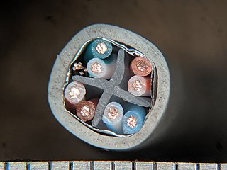
We would like to send I2C and 12v PWM for a DC motor over the same CAT6a S/UTP cable. I know this is not ideal, and "differential I2C" would be better, but for now standard I2C is what we have to work with. This answer says:
"Using [i2c over] CAT5 should be fine, as long as you select the pairing properly. At least never pair up clock and data. For I2C it means you should pair clock and ground, and supply and data. Since you have extra pairs, maybe twist clock with ground, data with ground, and then the remaining could be two supply-ground pairs. I don't recommend having two supply wires as a pair"
This makes sense for the pairing the I2C signals, and we are using an LTC4311 to help with I2C rise time over the distance. Therefore, two pairs in the CAT6a cable are available for 12v PWM to drive a standard brushed DC motor. The current will be <500mA, so 23 AWG should be fine. My question below is ultimately about how the PWM lines should be paired in the cable to minimize PWM<=>I2C crosstalk.
If we take a cross-section of a S/UTP CAT6 cable, it separates the pairs with a solid membrane:
For the purpose of posing my question, we label the cross-sectional areas as ABC and D:
 A | B
---+---
 C | D
Question:
How should they PWM motor lines be paired to minimize interference with the i2c line? Since two-pairs are available for PWM, there are a few options:
- Twist the +/- PWM lines into the same pair, eg: orange=PWM+12v, orange-stripe=PWM-GND
- Twist the +/- PWM lines into two pairs, eg: orange/green=PWM+12v, orange-stripe/green-stripe=PWM-GND.
- Dedicate one pair to each PWM conductor to treat the pairs as separate conductors, eg: orange/orange-stripe=PWM+12v, green/green-stripe=PWM-GND)
- others?
In which quadrant should each pair be located (PWM, PWM, SCL/GND, SDA/VDD)?
- Corner-to-corner: PWM=A,D and I2C=C,B
- or side-to-side: PWM=A,B and I2C=C,D
- others?
Other ideas are welcome, but keep in mind that ultimately the question is about PWM wire pairing and pair placement.
Thanks!

