2
\$\begingroup\$

I'm currently upgrading my wind-up torch - upon opening it, I found the manufacturers had been quite sneaky in that the circuit is EITHER windup OR battery powered - worse, the batteries are non-rechargeable, so there's no way to store the windup energy.

My plan is to change that. I have 10F, 2.3V capacitor. It's perfect, except for the fact that the dynamo produces a voltage of ~4V.

The first option is of course a zener. I actually have a bunch of 2.2V which would protect the capacitor fine. The problem is, of course, half the energy is going to be wasted across the diode short. Is there any way I can regulate the voltage below 2.3V without reducing the efficiency so significantly?

EDIT I've seen a few suggestions elsewhere that suggest putting a high-ohm resistor in series with the zener, presumably to minimize current through it (therefore maximising it into the capacitor). How effective would this be?

\$\endgroup\$
1
  • 2
    \$\begingroup\$ What's it powering, bulb or white LED? The simplest solution may just be two such capacitors in series. \$\endgroup\$
    – pjc50
    Commented May 4, 2013 at 11:30

4 Answers 4

4
\$\begingroup\$

Putting the 2.2V zener in parallel with the capacitor does not cut into the charging efficiency at all — the zener doesn't conduct at all until the capacitor is fully charged. But once it does conduct, it needs to absorb all of the energy coming from the dynamo, so make sure it's suitably rated.

\$\endgroup\$
2
\$\begingroup\$

You can use a buck regulator to convert higher voltages to regulated lower voltages quite efficiently but I question the need. It's a wind up torch and I don't think it's a big-deal to waste a few joules of energy by using an inefficient mechanism.

However, if you can't find a solution that adequately (albeit inefficiently) protects and charges your 10F cap then a buck regulator should be considered BUT I would also suggest a linear voltage regulator set to produce <=2.3V - it needs to be an adjustable type.

Whatever semiconductor mechanism you choose be aware that the dynamo may produce surges significantly above 4V so rate the circuit's voltage withstand capability with overhead. Maybe check what the output looks like using an oscilloscope.

EDIT - there is a suggestion from another answer that the LED needs more than 2.3V - in this case a different circuit is required in order to utilize the 10F cap. You'll need a boost regulator following the cap to achieve the higher drive levels to the LEDs.

\$\endgroup\$
2
\$\begingroup\$

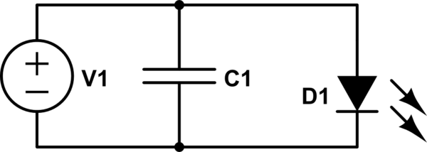
I would do this:

schematic

simulate this circuit – Schematic created using CircuitLab

Or this:
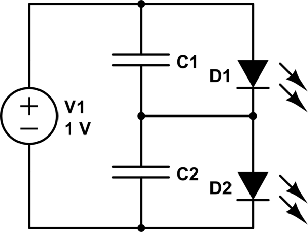
schematic

simulate this circuit

By putting two capacitors in series you double your cost, energy capacity, and maximum voltage.

You could use a reverse-biased zener for the diodes also, but using a forward-biased LED also gives you a visual indication of "fully charged".

The diodes are indicator LEDs you add, not the one already in the torch. They protect the capacitors from overcharging. You want to select the LEDs to do two things:

  1. have a forward voltage less than the absolute maximum voltage of the caps. I'd leave a 20% margin to be safe.
  2. absorb all the energy you can generate with the crank after the caps are charged without failing. If you can count on the operator to not continue cranking hard after the LEDs light, then this is substantially easier.

You say the dynamo voltage is about 4V, but really its a function of how fast the crank is turned. How hard the crank is to turn is a function of the current through the dynamo, so in the case where the caps are charged, so there is no charging current, the dynamo will be very easy to turn until you turn it fast enough to generate more than the LED forward voltage, at which point it will become markedly harder to turn. When the caps aren't charged, then the current/difficulty of turning/torque will be high even at low speeds/voltages.

Why is this? Consider the law of conservation of energy. Neglecting frictional losses, the mechanical power (torque times angular velocity) must equal the electrical power (voltage times current). Mechanical power is angular velocity times torque.

There are more complicated solutions, but I think they would be harder than buying a different product that operates the way you'd like without modification:

  • remove turns from the dynamo or decrease the strength of its permanent magnets to reduce the dynamo's output voltage. The dynamo's output voltage will be lower for a given speed, and the crank will be easier to turn for a given current, just as if you changed the mechanical advantage with a transmission.
  • use a buck-boost converter to reduce the voltage. With a switch you could use the same converter to upconvert the voltage on C1 to what's needed to drive the torch. You will still need something to absorb all the crank's energy once C1 is charged.
\$\endgroup\$
0
\$\begingroup\$

If you measured the dyne output voltage with no load on it, it might well be 4 V, but when loaded (and charging the cap), the voltage will fall. In face, in that case, charging a 2 V load from a 4 V source provides maximum power transfer to the load. Using a DC/DC might actually reduce your efficiency because it may limit the input voltage to ~ 4 V, thus restricting your available current.

\$\endgroup\$

Not the answer you're looking for? Browse other questions tagged or ask your own question.