What is your load current?
This influences the best answer.
A minority of regulators shut down gracefully and have little Vin to Vout voltage drop.
However, if it doesn't say so in the spec sheet it is quite likely not to do it in practice.
Yould could achieve close to what you want by using a bypass MOSFET across the regulator and switching it on with a voltage detector IC or similar. A TLV431 clamp regulator plus a bipolar pnp or p channel MOSFET (to invert TL431 signal) would do this. Extra current for the regulator is about 100 uA. You can get around 10-20 microamps using an LM385.
If you do not mind using "select on test" and some imprecision of changeover point you could use just resistors and 2 MOSFETs and get extremely low quiescent and operate currents - under 1 uA if necessary.
There are other possible solutions, but knowing load current will help.
Using MOSFETs to bypass regulator at low Vin.
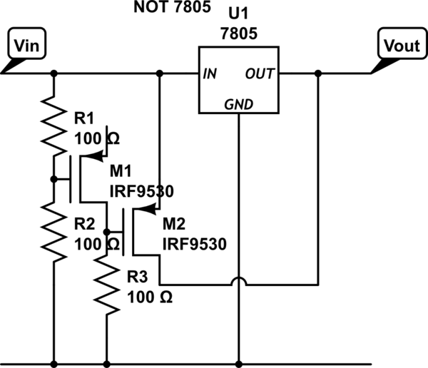
See circuit below.
This is my 1st use of the workbench cct drawer - please to excuse the several mistakes and cobby look. By all means fix it - I'm going to bed (7am plus, up all night, need to be up by 9:15). Connect M1 source to Vin. Regulator = LDO. MOSFETs are what works for you.
This circuit critically depends on the Vgs threshold voltage of M1 and the sharpness of the Vds - Ids turn-on knee. As the load has a substantial voltage range over which it will operate this "softness" of turn on may be acceptable.
For a sharp transition replace M1 with a TLV431 shunt regulator on the ground rails to M2 gate and move non gate end of R3 to Vin. Use TLV431 and not TL431 due to Vin_min being below TL431 range and also TLV431 gives lower Vclamp_min so FET driven harder.
When Vin too high R1-R2 turn on FET M1 which turns off FET M2 and regulator functions as normal.
When Vin falls too low M1 is turned off. M2 is turned on by R3 and the regulator is bypassed. It will still draw quiescent current via Vin to ground.

simulate this circuit – Schematic created using CircuitLab


