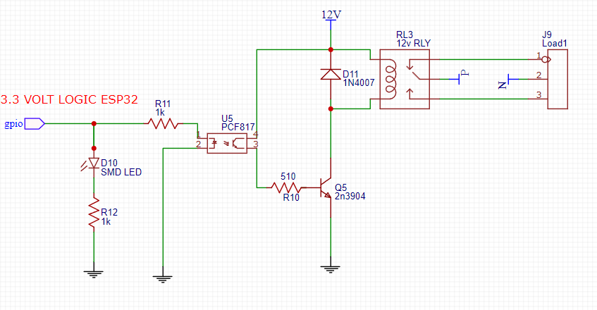
I want to know if my high side logic from 3.3 volt esp32 is right about linking a led on a gpio output to an optocoupler
-
1\$\begingroup\$ Are you sure you even need the optocoupler there? In your schematic your ESP and the 12V rail both have the same GND reference. The optocoupler is only required if you want to seperate the esp from the 12V rail. \$\endgroup\$– Patrick FiedlerCommented Oct 13, 2023 at 11:36
-
\$\begingroup\$ sorry about shematic i have made a mistake the GND are not sharing \$\endgroup\$– Khales NaimCommented Oct 13, 2023 at 11:51
-
\$\begingroup\$ the are 2 ground separate \$\endgroup\$– Khales NaimCommented Oct 13, 2023 at 11:51
-
\$\begingroup\$ @ScottSeidman the load is isolated via the relay, is it not? \$\endgroup\$– Patrick FiedlerCommented Oct 13, 2023 at 11:53
-
\$\begingroup\$ Looks OK to me. What is the relay coil resistance? \$\endgroup\$– JensCommented Oct 13, 2023 at 13:39
1 Answer
This Answer might not be 100% complete, but here are 2 things I'd change:
According to the PCF817 datasheet, the nominal forward current is 20 mA with a forward voltage of 1.2 V. That means R11 is way too large. The drop at R11 is 3.3 V - 1.2 V = 2.1 V @ 20 mA, so R11 should be ~ 105 Ohm.
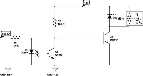
The way you wired up the output side will probably not work correctly. When the optocoupler is off, your transistor's base is floating, which should be avoided. I'd probably do something like this:

simulate this circuit – Schematic created using CircuitLab
That way the Relay should be default on and triggering the opto pulls Q5's base to GND -> state switches to off.
Be aware though, I haven't tried/tested/simulated this, so it might not work perfectly, but that's where I'd start.
-
\$\begingroup\$ The ESP32 GPIO cannot deliver 20 mA and 2 mA are enough as forward current for the coupler. This would provide > 1 mA base current and up to 100 mA relay coil current in the OP's original circuit. \$\endgroup\$– JensCommented Oct 13, 2023 at 13:37
