We have a 2G11-socket 36W germicidal UVC lamp in our air ducts (Honeywell UC36W1006), and since UV-C LEDs are readily available, I thought maybe I could make a PCB with a bunch of UV-C LEDs on it as a longer-lasting lower-power replacement.
This study shows that a dose of 50mJ/cm2 will kill 90% of bacteria and viruses (1 log reduction), so very few LEDs would be required in the plenum (assuming a 30-second exposure).
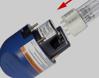
I could just run DC to the new boards, but wondered if it would be feasible to use the existing twist-lock enclosures with a pin-compatible connection to the existing fluorescent driver outputs. The PCB would plug directly into the blue socket below in place of the fluorescent lamp:
I've looked around quite a bit, and while there are many places selling 2G11 bulb replacements, I can't find any technical documentation on the pinout. Here's what I've found so far:
- It looks like 2G11 is also implemented as "PL-L 4P" (Philips Linear Compact Fluorescent Lamps).
- This video shows lighting it with a ballast that has a 430V output.
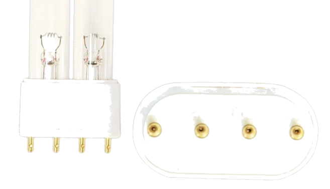
There are 4 pins, two pairs to illuminate two elements. The tube is a loop at the far end (not pictured) so (I think) the left and right elements would be the same as those at each end of a linear fluorescent tube:
Question:
How can I use those 4 pins to get ~6V DC to illuminate UV-C LEDs?
Others have made 2G11 LED lamps (but not UV), so clearly it can be done...but what components are involved in stepping down the lamp input to a DC level for LEDs?


