0
\$\begingroup\$

I need to make an RC oscillator with a Wien bridge and JFET amplitude stabilization, I have a schematic, but no formulas on how to calculate the values. I tried to look around the internet, but found nothing that works for me. Here is the schematic: RC oscillator
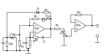
Also the frequency should be 1 kHz, the amplitude 0-5 Vef and the output resistance lower than 100 Ω.

Here you can find similar schematics: https://www.sse-najizdarne.cz/dokumenty/studijni_materialy/ov/uc_text_oscil%C3%A1tory.pdf

\$\endgroup\$
6
  • 2
    \$\begingroup\$ Tadeas.grohmi - Hi, (a) You said: "I have a schematic, but no formulas on how to calculate the values" It sounds like you got the schematic from somewhere else (as you'd know the calculations if you had designed it). In order to comply with the Stack Exchange rule for referencing, which applies to material copied or adapted from elsewhere, we need you to edit your question & add a link to the schematic's source (or a written citation if it's an offline source). (b) Please see the main site rules in the tour & help center as they differ from typical forums. Thanks. \$\endgroup\$
    – SamGibson
    Commented Oct 21, 2023 at 15:47
  • \$\begingroup\$ Why don't you test it in a simulator because formulas don't usually help when pots are involved or JFETs. \$\endgroup\$
    – Andy aka
    Commented Oct 21, 2023 at 16:10
  • \$\begingroup\$ Here is an app note with values, see figure 3. pdfserv.maximintegrated.com/en/an/AN3846.pdf Note that I built this and couldn't get it to work. I am always working on multiple projects. so, if one frustrates me to much, I put it aside. I may come back to it someday. \$\endgroup\$
    – Mattman944
    Commented Oct 21, 2023 at 16:37
  • \$\begingroup\$ Thanks for the notes. Im working on a simulation, but its a pain to get the wave to look like a good sin signal. \$\endgroup\$ Commented Oct 21, 2023 at 17:30
  • \$\begingroup\$ @Tadeas.grohmi - Hi, I see you added a link to a PDF, mentioning that it has "similar schematics". However I did not find the actual schematic which you copied into the question. Therefore currently your question still breaks the site rule about containing copied material without a reference for that material (adding a reference to similar material does not count). || Please can you explain what is stopping you from adding a reference to the source of that schematic? Then we can figure out how we can reasonably comply with the site rule. Thanks. \$\endgroup\$
    – SamGibson
    Commented Oct 21, 2023 at 20:42

3 Answers 3

2
\$\begingroup\$

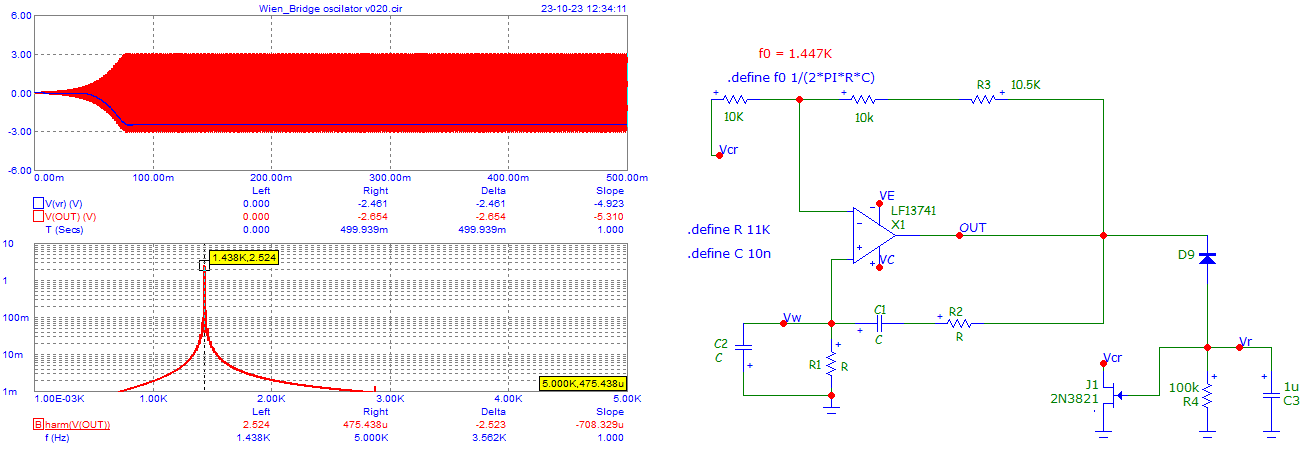
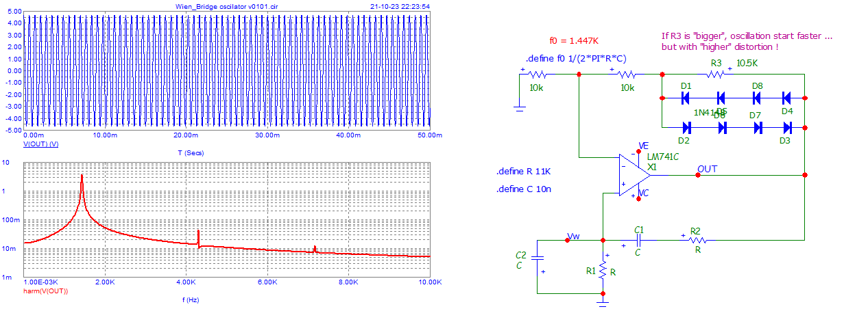
Just try this simple circuit ... for starting the search.
Then you can add the JFET and the other components.
The last opamp is just a voltage "follower".

enter image description here

Adding JFET ...

enter image description here

\$\endgroup\$
1
\$\begingroup\$

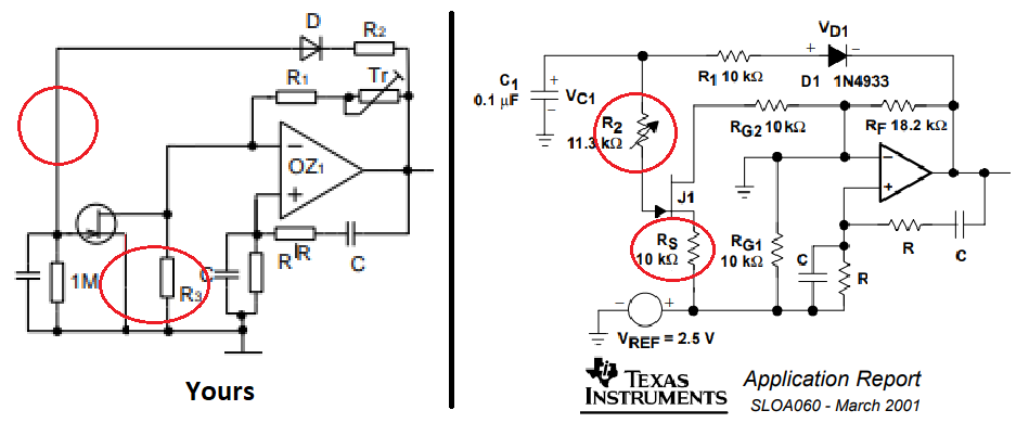
Your circuit is different to the circuit recommended by Texas instruments:

Wien bridge oscillator

\$\endgroup\$
1
\$\begingroup\$

Here are some basics:

  • Oscillation frequency: w=1/RC. You should try to use two resistors R in the lower kOhm range and two capacitors not too small (no pico-Farads) and not too large (not in the upper micro-Farad range).
  • The nominal gain of the opamp amplifier must be A=+3 (in practice some % larger because of the FET stabilization)
  • The time constant of the FET-path Tf=C1*Rf (Rf is the effective R connected with C1) should be app. 10 times larger (at least) as the oscillation period T=2Pi * RC
\$\endgroup\$

Your Answer

By clicking “Post Your Answer”, you agree to our terms of service and acknowledge you have read our privacy policy.

Not the answer you're looking for? Browse other questions tagged or ask your own question.