2
\$\begingroup\$

I am implementing what I've learned over the past couple of days. This relates mainly to the simulation of a voltage regulator.

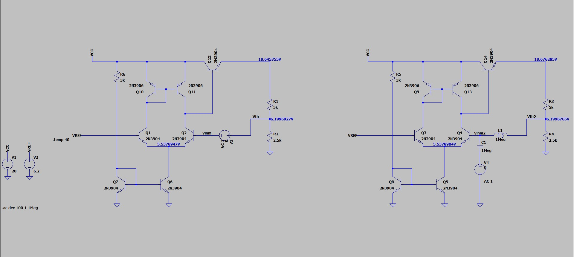
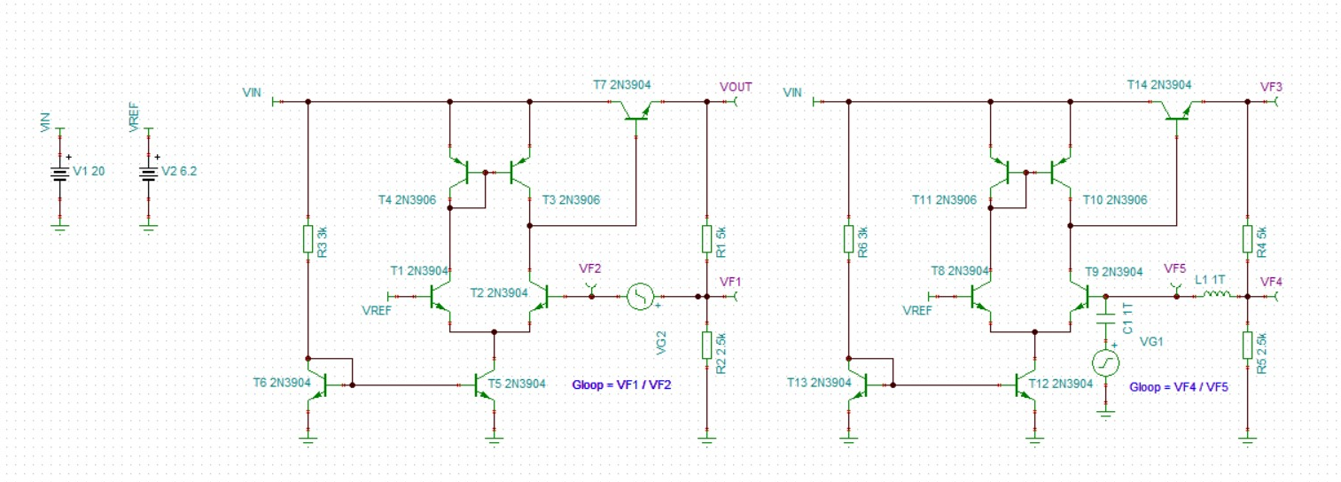
I built the (roughly) same circuit in both TINA TI and LTspice to determine the value of the loop gain of the circuit.

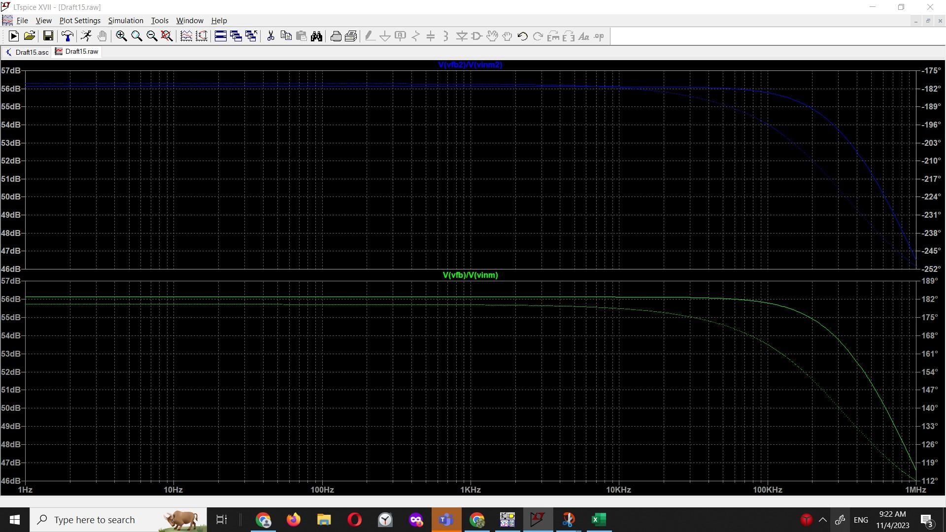
The results are quite different. For the TINA TI simulation the loop gain is 43dB, while for the LTspice simulation the loop gain is 56dB. One is within the desired design parameters, the other is not.

I've implemented the sims with both the traditional breaking the loop + test voltage, as well as with voltage injection (?).

TINA TI sim:

enter image description here

The results are as follows:

circuit on the left: 148.4 circuit on the right: 147.8

LTspice sim:

enter image description here

LTspice results: enter image description here

Where am I wrong and why?

EDIT 1: I did try and change the beta of transistors to see if there any differences between TINA TI, but the impact was minimal.

EDIT 2: I did try to set the inductor and capacitor to be 1TH/1TF, but it didn't work. Also changed the values in the TINA simulation and I did not sight any difference.

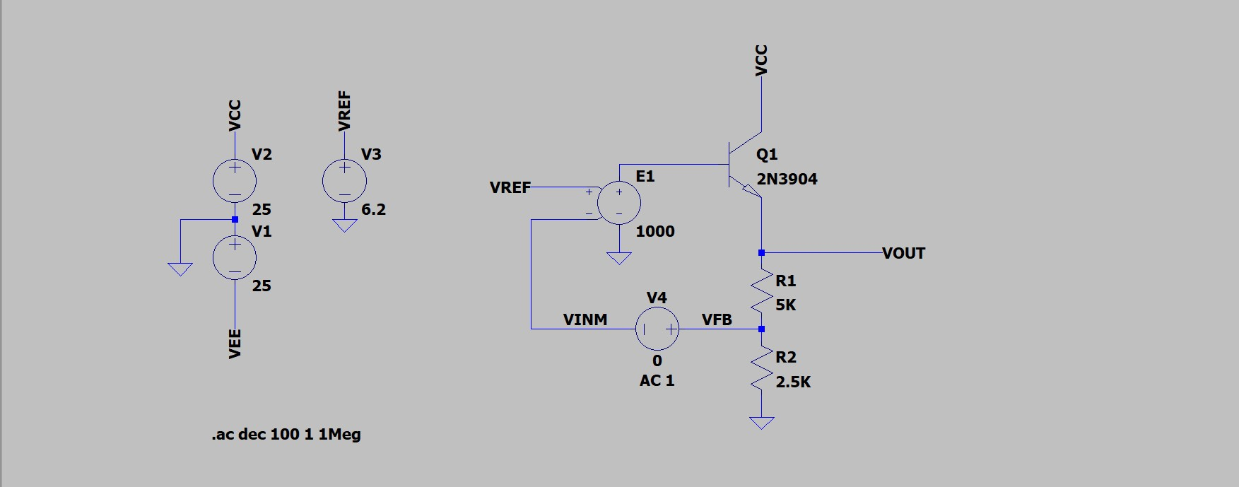
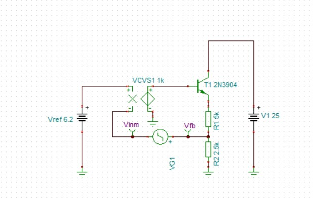
EDIT 3: I replaced the error amplifier with a Voltage Controlled Voltage Source and decided to compare the results between TINA and LTspice. The results were very close to each other. Simulated circuit is shown below:

LTspice sim: enter image description here

TINA sim: enter image description here

So I'd say the problem is not with the method of finding loop gain, but something about the way the sims treat the more complex circuit?

\$\endgroup\$
20
  • 1
    \$\begingroup\$ 1 megahenry does not equal 1 terahenry \$\endgroup\$
    – Andy aka
    Commented Nov 3, 2023 at 21:01
  • \$\begingroup\$ The LTspice simulation behaves suspiciously when I set the inductance and capacitance at 1 Tera something. \$\endgroup\$ Commented Nov 3, 2023 at 21:02
  • \$\begingroup\$ Try setting Tina to 1 megahenry then. It probably won't make much difference but, it looks like an anomaly at the moment. \$\endgroup\$
    – Andy aka
    Commented Nov 3, 2023 at 21:07
  • \$\begingroup\$ Just tried it, no difference from the initial results. \$\endgroup\$ Commented Nov 3, 2023 at 21:08
  • \$\begingroup\$ I'd suggest using native primitives for measuring loop gain. If a given SPICE program does not provide them, or doesn't document it, I suggest not using it for this simulation. Furthermore, the results are quite useless anyway, since in a real circuit the temperature differences and mismatches between transistors will drive performance of the circuit. In other words, in practice the gain spread you'll get at various operating temperatures and transistor parameter spreads will vastly exceed the "difference" you're seeing between simulated values that don't represent reality well anyway. \$\endgroup\$ Commented Nov 3, 2023 at 21:22

2 Answers 2

1
\$\begingroup\$

I suspect the difference is due to the BJT models being slightly different between TINA and LTspice. The parameter values to compare would be those that determine the following static (DC) transfer functions:

  1. base voltage to collector current, and
  2. collector current to collector voltage.

The LTspice help file explains this as follows:

The DC model is defined by the parameters Is, Bf, Nf, Ise, Ikf, and Ne which determine the forward current gain characteristics, Is, Br, Nr, Isc, Ikr, and Nc which determine the reverse current gain characteristics, and Vaf and Var which determine the output conductance for forward and reverse regions. Three ohmic resistances Rb, Rc and Re, are included, where Rb can be high current dependent.

Listing these parameters from the help file in the groups as mentioned above:
Group 1:
Is Transport saturation current
Bf Ideal maximum forward beta
Nf Forward current emission coefficient
Ise B-E leakage saturation current
Ikf Corner for forward beta high current roll-off
Ne B-E leakage emission coefficient

Group 2:
Br Ideal maximum reverse beta
Nr Reverse current emission coefficient
Isc B-C leakage saturation current
Ikr Corner for reverse beta high current roll-off
Nc B-C leakage emission coefficient

Group 3:
Vaf Forward Early voltage
Var Reverse Early voltage

Group 4:
Rb Zero-bias base resistance
Re Emitter resistance
Rc Collector resistance

The above parameters affect the static transfer characteristics (zero frequency) of input voltage (Vb) to output voltage (Vc), I have deliberately omitted temperature dependencies, and parameters that affect dynamic behaviour, such as:-
Vtf Voltage describing Vbc dependence of Tf

To see if it is the simulator or the model causing the gain difference you are seeing, I suggest copy the BJT models from one simulator to the other and see if the results are identical. Then compare the two original BJT models, looking at the values for the parameters mentioned above, to see what differences there are.

Getting accurate models for BJTs is non-trivial, here are some good starting points:
How do I find or calculate BJT parameters for LTspice?

References for writing spice model code?

\$\endgroup\$
8
  • 1
    \$\begingroup\$ Yeah, that was it. The biggest influence seems to be the early voltage, which I guess makes sense as the loop gain depends on the output impedance of the transistors in the current mirror/ differential pair. \$\endgroup\$ Commented Nov 4, 2023 at 9:48
  • \$\begingroup\$ OK, good. So did the two simulators, TINA and LTspice, give the same results when the models were identical? An upvote would be nice. :-) \$\endgroup\$ Commented Nov 4, 2023 at 10:03
  • \$\begingroup\$ First of all, thank you! Yes, when using the models from TINA in LTspice the loop gain was identical to the original simulation in TINA. What annoys me terribly at the moment is that the quality of my voltage regulator depends on the early voltage of the transistors. \$\endgroup\$ Commented Nov 4, 2023 at 10:13
  • \$\begingroup\$ No worries. Yes, the early voltage (aka the output impedance) of small signal transistors is definitely non-ideal. Ideally, it should be infinite - so that a small change in current results in a large voltage swing. Alas, in practise, the output impedance is far less than infinite. And it seems that BJT physics conspires against us - BJT construction techniques that increase transconductance seem to reduce output impedance, and vice-versa. \$\endgroup\$ Commented Nov 4, 2023 at 10:35
  • \$\begingroup\$ Suggestion: try a cascode (common-base) between the diff pair and their load transistor. This is an old trick to try to increase gain. However, you may find it has little effect at low frequencies, but may be very beneficial at higher frequencies. electronics.stackexchange.com/questions/535843/… \$\endgroup\$ Commented Nov 4, 2023 at 10:41
0
\$\begingroup\$

Just tried now with microcap v12

enter image description here

\$\endgroup\$
1
  • \$\begingroup\$ Thank you for simulating the circuit. It appears I should be more careful to transistor model parameters. \$\endgroup\$ Commented Nov 4, 2023 at 13:31

Your Answer

By clicking “Post Your Answer”, you agree to our terms of service and acknowledge you have read our privacy policy.

Not the answer you're looking for? Browse other questions tagged or ask your own question.