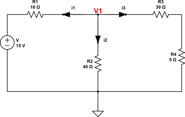
Learning to draw
From your earlier question and this one I think I'd recommend gaining some practice redrawing schematics in different ways. Some schematics are the logical equivalent of a Gordian Knot and desperately need to be redrawn. (Hopefully, you encounter these later on when you are more experienced in redrawing.) Others can be made simpler in order to help you understand them for analysis, but are terrible for figuring out how to wire them up on a breadboard.
There are different audiences for schematics. And not everyone who draws them are equally good at the task. So get good at this process, yourself. It's worth the effort and will pay off well over time. And knowing how to draw schematics takes you more than halfway towards understanding how to analyze them.
Here's your schematic shown in a schematic targeting someone without any electronics experience but with some parts, wire, and a power supply:
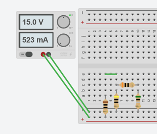
This is not a very good schematic for analysis, though. It is purely designed to make construction easy to follow and where the least amount of wiring is involved.
For nodal analysis, one of these would be much better:
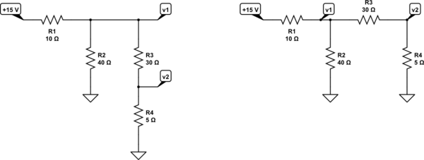
simulate this circuit – Schematic created using CircuitLab
But neither of those are all that helpful for mesh analysis. The following would be better for mesh as the loops are clear:
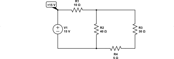
simulate this circuit
Practice redrawing schematics until it feels fairly natural to you.
Nodal analysis
The current direction isn't important. In fact, you can mostly ignore that question when faced only with resistors.
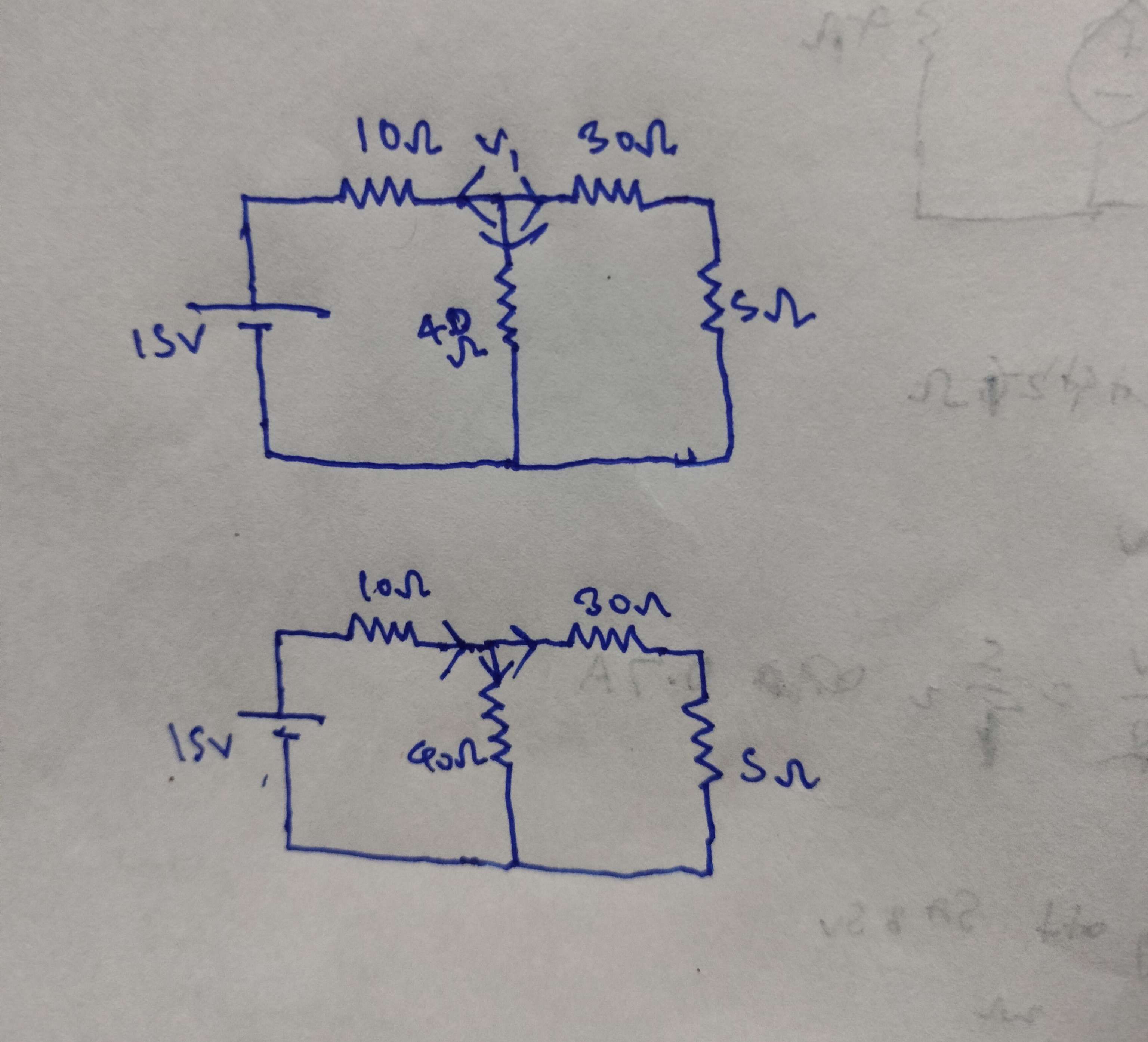
Let's ignore current direction and just do nodal analysis on your schematic:

simulate this circuit
There are just two unknown nodes. (Ground and \$+15\:\text{V}\$ are known.) So let's completely avoid assigning a specific current direction and instead say that the current goes both ways at once. (This isn't unlike mesh analysis, which can often claim that a single device carries two loop currents at the same time.) By deciding it goes both ways, we don't have to make a choice.
Let's start with node \$v_1\$:
$$\begin{align*}
\frac{v_1}{R_1}+\frac{v_1}{R_2}+\frac{v_1}{R_3}&=\frac{+15\:\text{V}}{R_1}+\frac{0\:\text{V}}{R_2}+\frac{v_2}{R_3}
\end{align*}$$
To read the above, imagine that the left side has all the current arrows pointing away from node \$v_1\$ towards the other nodes. And that the right side has all the current arrows pointing into node \$v_1\$ from the other nodes. These of course must balance out.
So, there's no need to be forced to make a choice. Instead, choose both ways at once! You can't go wrong when you treat both directions as simultaneously true!!!
So, the other equation would then be:
$$\begin{align*}
\frac{v_2}{R_3}+\frac{v_2}{R_4}&=\frac{v_1}{R_3}+\frac{0\:\text{V}}{R_4}
\end{align*}$$
Using freely available SymPy, SageMath, and Python:
for i in list(solve([
    Eq(v1/r1+v1/r2+v1/r3,15/r1+0/r2+v2/r3),
    Eq(v2/r3+v2/r4,v1/r3+0/r4)],[v1,v2]).values()):
        i.subs({r1:10,r2:40,r3:30,r4:5})
420/43  # v1 = 9.76744186046512
60/43   # v2 = 1.39534883720930
And a separate LTspice run provides similar results:
V(v1):   9.76744     voltage
V(v2):   1.39535     voltage
The point here is that you can save yourself some grief and just not worry about current directions when dealing with resistors.
Both directions are correct!
