1
\$\begingroup\$

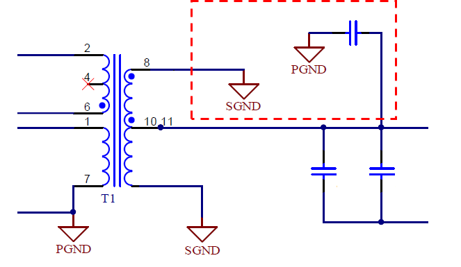
I ask this question because I saw this in an Altium article:


enter image description here

In power systems, be careful how you use a capacitor to ground to ensure a consistent ground reference. Y-rated capacitors are best in this application, where you need to remove DC offsets between planes while still providing galvanic isolation and high-frequency EMI filtering.


As far as I know, capacitors block DC current and there is usually a non-zero DC voltage between a general ceramic capacitor. Y-caps are specially designed for safety purposes. It is placed between live and earth and is open when fails.

My questions are:

  1. Is practical Y-rated capacitor such a special capacitor that can even set two isolated ground references to the same DC voltage?
  2. I think 'remove DC offset' means having the same DC voltage. Do I understand 'remove DC offset' correctly?

(Here is a similar question but I cannot get a exact answer)

\$\endgroup\$
2
  • \$\begingroup\$ I think they mean that the transformer is removing the DC offset of an input signal relative to PGND while the capacitor is still allowing the grounds to be connected for AC signals. The capacitor does not remove the DC offset between PGND and SGND which are probably at different DC levels relative to one another. \$\endgroup\$ Commented Nov 8, 2023 at 1:57
  • \$\begingroup\$ I've read and re-read the Altium reference, and it still doesn't make sense. Looks like some mis-wording to me. \$\endgroup\$
    – SteveSh
    Commented Nov 8, 2023 at 2:00

2 Answers 2

1
\$\begingroup\$

No, the wording is bad. Capacitors or Y capacitors do not remove DC offsets by making the DC voltage same over the capacitor

Capacitors specifically allow an DC offset so you are free to define the DC voltage over the capacitor, which also allows you to set or remove DC offset between two circuits, so basically, they allow two circuits to be at different DC offsets.

So since one side of the capacitor can be at different DC offset than the other, in common language it can be said that the capacitor removes DC offset, so that DC offset of some circuit does not affect the DC offset of the other circuit.

Which makes both your questions have incorrect assumptions.

  1. Y capacitors are like any normal capacitor but just rated and guaranteed for handling mains voltage and even more and fail safely open in a fault situation. Y capacitors are used to keep DC voltage difference but allow AC voltage waveforms to be equal on both sides, i.e. EMI reasons.

  2. As explained, no

\$\endgroup\$
0
\$\begingroup\$

Y-rated capacitors are best in this application, where you need to remove DC offsets between planes while still providing galvanic isolation and high-frequency EMI filtering.

My primary language is not English but what I understand from "removing DC offset between grounds" is to bring them to the same DC potential.

Now the bolded statement above makes no sense to me because if a Y-cap was used to "remove" the DC offset between grounds then they wouldn't be isolated. If we want to remove the DC offset between grounds then why would we use a Y-cap? We would short them instead!

This makes my answer to both of your question "No".

\$\endgroup\$
8
  • \$\begingroup\$ Well for example if you make a mains input switch mode power supply, you definitely need to remove the DC offset of the mains input side for the low voltage output side to float. Because your mains "ground" is likely looking like half-sine going between 0V and -325V. So yes the wording is kind of bad for what it means to remove a DC offset. \$\endgroup\$
    – Justme
    Commented Nov 8, 2023 at 8:40
  • \$\begingroup\$ @Justme Because your mains "ground" is likely looking like half-sine going between 0V and -325V. with respect to where? \$\endgroup\$ Commented Nov 8, 2023 at 9:01
  • \$\begingroup\$ If you take in 230V mains Live which is AC and Neutral which is technically 0V and bonded to Earth, and rectify that to a capacitor, that is the waveform of capacitor negative terminal in reference to 0V Earth or Neutral. \$\endgroup\$
    – Justme
    Commented Nov 8, 2023 at 9:05
  • \$\begingroup\$ @Justme you said mains "ground" is likely looking like half-sine going between 0V and -325V in your first comment, and that is the waveform of capacitor negative terminal in reference to 0V Earth or Neutral. in the 2nd. When you say "mains ground" I understand PE, not the ground (or return path) of rectified DC. That's why I asked "w.r.t where?". Anyway, the rectified DC ground (bulk cap's negative) will be a sine wave swinging between 0 and minus mains peak (-325V) which means an offset of -160V w.r.t. PE. But I couldn't understand the relation between this offset and output isolation... \$\endgroup\$ Commented Nov 8, 2023 at 9:48
  • \$\begingroup\$ ... you definitely need to remove the DC offset of the mains input side for the low voltage output side to float. Why do we need to remove the HV input's DC offset w.r.t. PE (presumably) , which can't be removed, to have floating output? \$\endgroup\$ Commented Nov 8, 2023 at 9:50

Your Answer

By clicking “Post Your Answer”, you agree to our terms of service and acknowledge you have read our privacy policy.

Not the answer you're looking for? Browse other questions tagged or ask your own question.