5
\$\begingroup\$

I apologize if this an obvious question. This is my first time adding lithium-ion battery components to a circuit and I'm trying really hard to do all my homework and understand the function of everything to avoid accidental explosions.

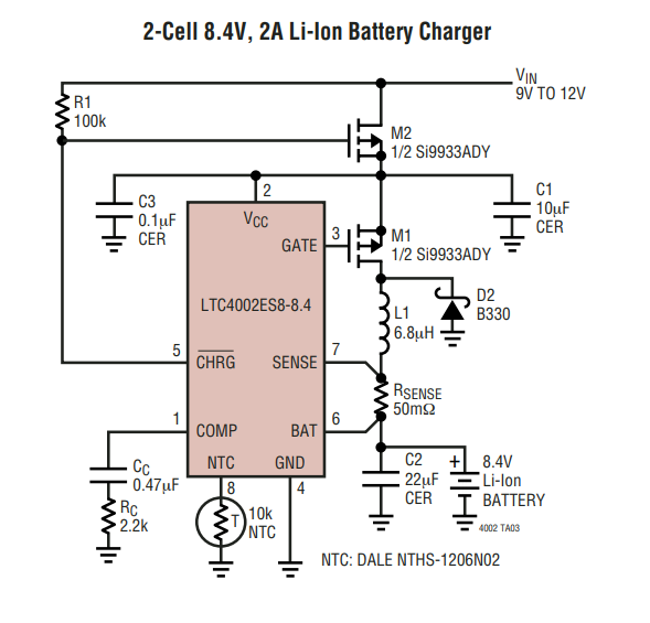
I'm adding this battery charger IC to a circuit. I proceeded through the datasheet and did all my calculations / considerations expecting that at some point it would mention the purpose of the second P-MOSFET in the 8.4V diagram (see below,) but it never does.

enter image description here

In the single cell example a simple Schottky diode is used to isolate the input, and I'm assuming that is what the MOSFET is doing here as well. I've tried to break it down so I can understand its function.

Here is how I understand the circuit to work:

According to the datasheet, the charge pin is driven low when the device is in charging mode. When it's outside of charging mode (either because the input was disconnected or the device finished charging) the pin goes to high impedance, causing the pin to float. Charging mode starts when Vcc is greater than programmed battery voltage and stops after 3 hours.

So Vin gets plugged in, the body diode of M2 provides a path for Vcc to be driven to Vin, causing charge mode to start and CHRG to drive low which triggers M2 (which isn't necessary because we already have voltage passthrough because of the body diode.)

Then charging ends, CHRG goes to high impedance, causing the M2 Vgs to be positive closing M2 (accomplishing nothing because again we have the body diode of M2 passing voltage from Vin to Vcc.) If Vin is unplugged/drops to 0V before charging is done, then the IC goes into shutdown, which causes the same to occur.

Am I missing something here? It feels like there is no added benefit to doing the circuit like this. In other examples I've seen online other people appear to just use diodes, so why is the datasheet like this?

\$\endgroup\$

1 Answer 1

5
\$\begingroup\$

You're right that M2's body diode passes voltage through, but it has a voltage drop of typical -0.7 V and max -1.2 according to the datasheet. Instead of having the diode turn current into heat when charging, the MOSFET is turned on for much lower voltage drop.

In the single cell example a simple Schottky Diode is used to isolate the input, and I'm assuming that is what the MOSFET is doing here as well.

Correct. That's the main function of the M2 MOSFET. You get better efficiency than with a regular diode.

\$\endgroup\$
5
  • 1
    \$\begingroup\$ Ah that makes sense, and the datasheet was just trying to show off different ways of doing it. For them not to mention it in the datasheet, I knew it had to be something like that... but I wasn't 100% certain. I appreciate your answer! \$\endgroup\$
    – J05H B3AN
    Commented Nov 11, 2023 at 14:11
  • \$\begingroup\$ Thank you! I have stared at those circuits too and had doubts, but there's always some cleverness to them :) \$\endgroup\$
    – MiNiMe
    Commented Nov 11, 2023 at 14:28
  • \$\begingroup\$ I think they want to avoid a discharge trough the IC via Vcc when Vin goes lower than the battery voltage. \$\endgroup\$
    – Fredled
    Commented Nov 11, 2023 at 20:22
  • 1
    \$\begingroup\$ @Fredled You're right, except it's not from Vcc but through M1's body diode. \$\endgroup\$
    – MiNiMe
    Commented Nov 11, 2023 at 20:25
  • 1
    \$\begingroup\$ @J05HB3AN You are right. I didn't notice the different orientation. It's very lazy schematic design and can cause confusion. I deleted my answer. \$\endgroup\$
    – Fredled
    Commented Nov 11, 2023 at 20:25

Your Answer

By clicking “Post Your Answer”, you agree to our terms of service and acknowledge you have read our privacy policy.

Not the answer you're looking for? Browse other questions tagged or ask your own question.