1
\$\begingroup\$

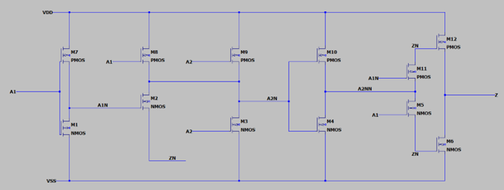
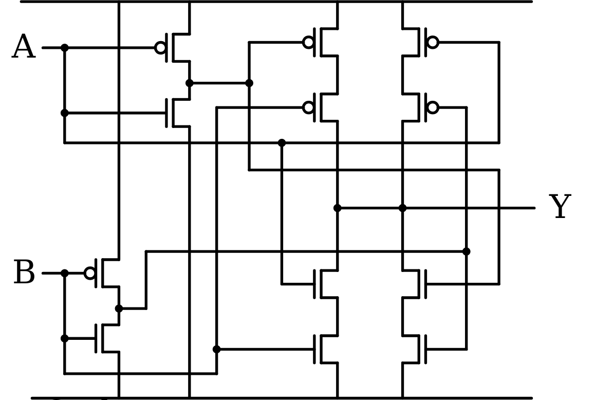
I have come across this circuit for an XOR gate (see below) using 12 transistors in CMOS technology. I am having trouble understanding the circuit, mainly in identifying the logic gates.

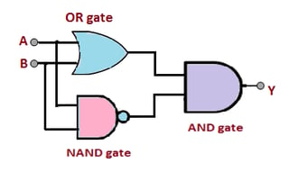
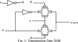
I know that an XOR can be made using a NAND, an OR and an AND (see example below). But there are other alternatives, and perhaps this circuit is implementing other logic I can't identify. As some other users already suggested, perhaps this implementation uses transmission gates (an example is also presented below)

Can someone help me? Perhaps the circuit can be rearranged to make more sense to me.

enter image description here

enter image description here enter image description here

\$\endgroup\$
7
  • 1
    \$\begingroup\$ Note that there are ways to make an XOR gate using transmission gates instead. This isn't that, but your statement that "a XOR is made using a NAND, an OR and another AND" is not always true. \$\endgroup\$
    – Hearth
    Commented Nov 11, 2023 at 19:45
  • \$\begingroup\$ @Hearth: "... make an XOR gate using transmission gates instead. This isn't that, ..." Actually, this is exactly that. If you look closely at the node names, M5 and M11 form a transmission gate between A2NN and ZN. \$\endgroup\$
    – Dave Tweed
    Commented Nov 11, 2023 at 21:00
  • 1
    \$\begingroup\$ But this circuit is not correct anyway. The transmission-gate XOR normally has only 6 transistors. The circuit shown in the first diagram above will short the power supply when A1 is low and A2 is high. \$\endgroup\$
    – Dave Tweed
    Commented Nov 11, 2023 at 21:14
  • \$\begingroup\$ @DaveTweed thank you for the clarification but this circuit does need to have 12 transistors. Can you please clarify what you mean about the supply being shorted? \$\endgroup\$ Commented Nov 11, 2023 at 21:44
  • 1
    \$\begingroup\$ Your image is very fuzzy, but if I'm reading it correctly, A1 low turns on M8, while A2 high simultaneously turns on M3. \$\endgroup\$
    – Dave Tweed
    Commented Nov 11, 2023 at 21:58

1 Answer 1

4
\$\begingroup\$

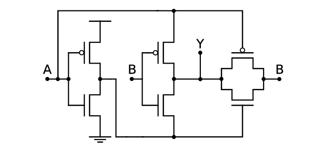
The transmission-gate XOR should have only 6 transistors:

6-transistor XOR schematic

source

It works as follows:

  • If A is high, then the transmisison gate (the two transistors on the right) is cut off. The inverter in the middle is operational, and drives the output to be "not B" — i.e., B XOR 1.

  • If A is low, then the inverter in the middle does not work, but the transmission gate connects B directly to the output — i.e., B XOR 0.

And just for completeness, the standard CMOS 12-transistor XOR gate looks like this:

12-transistor XOR schematic

source

\$\endgroup\$
0

Your Answer

By clicking “Post Your Answer”, you agree to our terms of service and acknowledge you have read our privacy policy.

Not the answer you're looking for? Browse other questions tagged or ask your own question.