1
\$\begingroup\$

My 0.5" (1/2 inch) iron core inductor did not have a high inductance due to (I assume) eddy currents.

Theory seems to suggest that ferrite cores are the ticket to increase inductance.

I ordered several of these ferrite cores, which are listed to have a 2300 initial permeability.

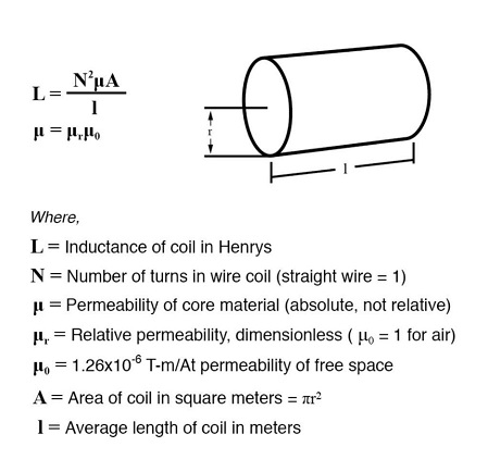
U used this equation to predict the measured inductance:

enter image description here

That gives 32.8 mH for a 9.5 mm diameter ferrite rod over a 10 mm coil length (width of coil around rod.)

enter image description here

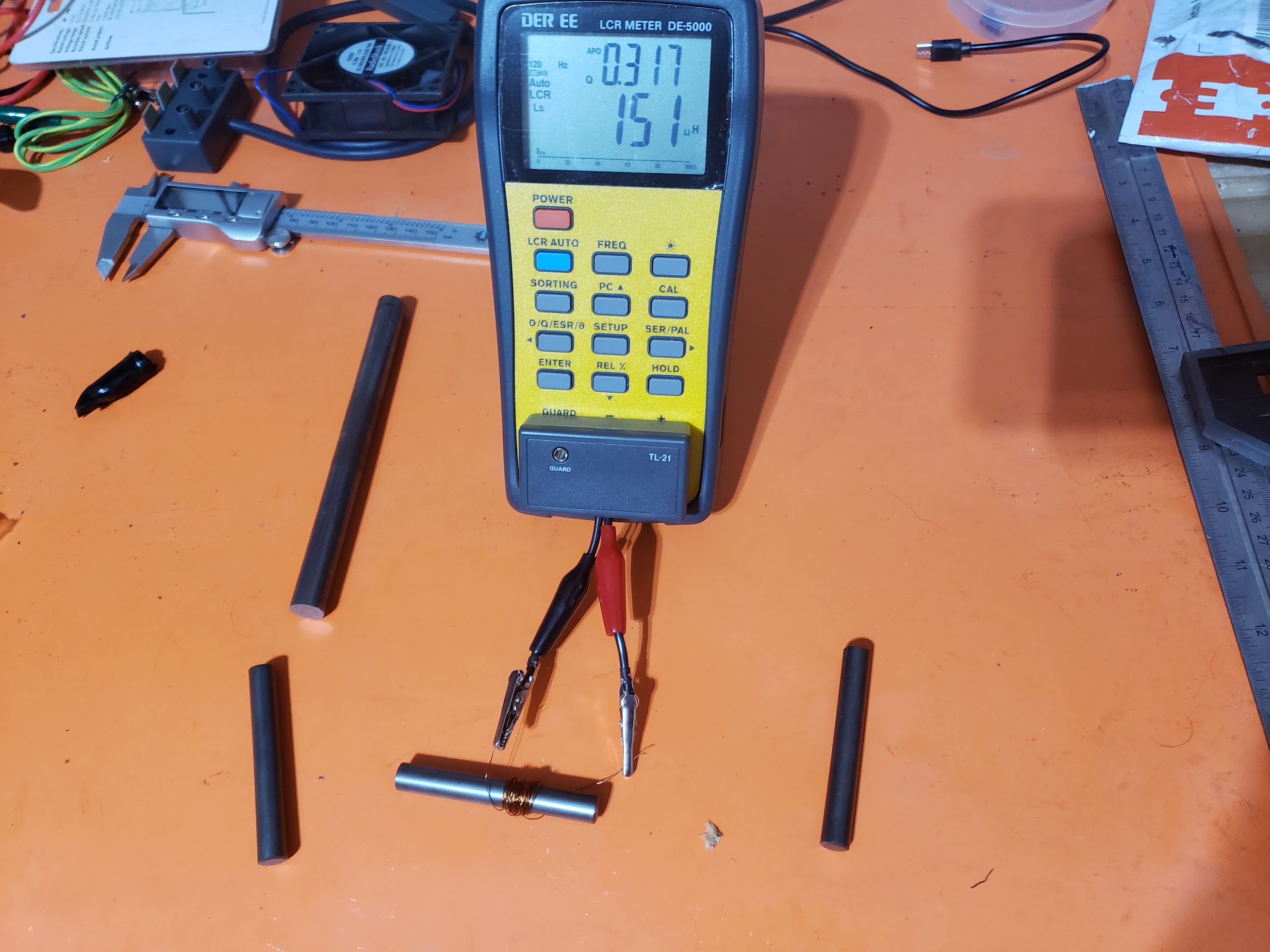
Instead, a verified LCR meter gives 151 micro-H or 0.151 mH.

measured result

This would suggest the relative permeability of the rod to only be around 11.

calc

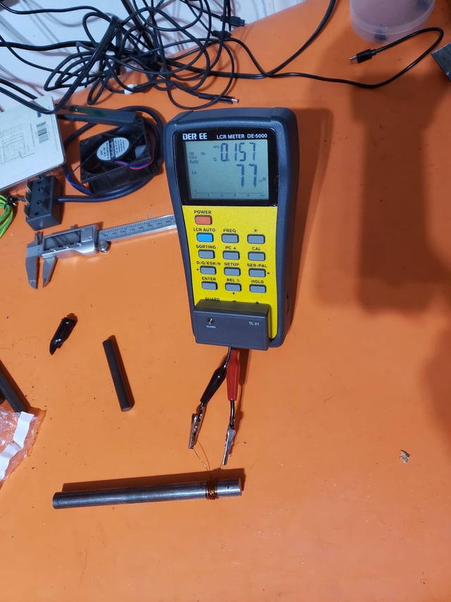
This is only a step above the iron rod permeability/inductance (77 micro-H for 35 turns.)

iron rod measurement

Another thing to note is that length seems to matter here because when these ferrite rods are touched to one another, the inductance increases. This too may seem to disagree with the equation that indicates the inductance is turns per unit length.

Can someone please help my ignorance as to why measurements are not matching the theory/calculations? I want to make a 10 H inductor by bundling the ferrite rods together, but there is no need until I can verify at least one is acting according to predictions.

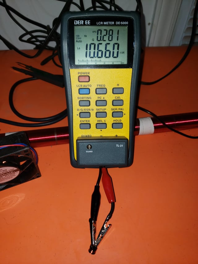
Side note: Verification of LCR meter on a known 10 mH inductor.

enter image description here

\$\endgroup\$
4
  • 1
    \$\begingroup\$ I don’t think you can use 2300 as permeability in this equation. Open Ferrite (huge air gap) cores increases inductance usually 10-th times comparing to air cores. Btw, 150uH for 40 turns seems ok to me. \$\endgroup\$ Commented Nov 16, 2023 at 1:17
  • 1
    \$\begingroup\$ Consider using a ferrite toroid or EI core instead; you'll get much higher inductance. \$\endgroup\$
    – Hearth
    Commented Nov 16, 2023 at 1:28
  • \$\begingroup\$ Thank you for your insight. What permeability is to be considered here other than 2300? Where else would 2300 be utilized? Are these inductance equations insufficient? \$\endgroup\$
    – zdanman
    Commented Nov 16, 2023 at 2:32
  • 1
    \$\begingroup\$ @zdanman The permeability is 2300 for part of the magnetic path, and 1 for the rest of it. most of the magnetic path has a permeability of 1, really, because it's just air. \$\endgroup\$
    – Hearth
    Commented Nov 16, 2023 at 5:17

4 Answers 4

3
\$\begingroup\$

You are way off base with your inductance calculations, and seem to be ignoring the advice that calculating the inductance is more complicated than just multiplying by the permeability of the core. There is a lot of material available on this exact problem stemming initially from the use of ferrite rods from their use as ferrite rod antennas. If you google 'inductance of ferrite rod antenna' you will get a lot of info.

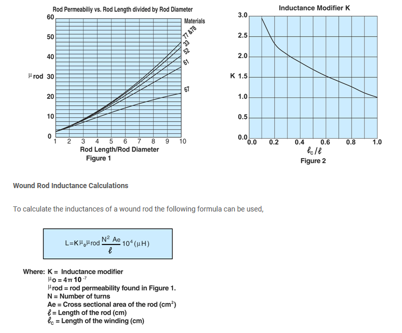
This is actually quite a complex problem to solve from first principles. However, if you look on the manufacturer's website for your rod they give you the exact data you need:

https://fair-rite.com/product/rods-4078377511/

enter image description here

if you plug your numbers into their formula you get L = 159uH. Note that your coil is short so estimating K from their graph is hard, and your coil is pretty messy and not centered on the rod.

This is not that far from your measurement.

This doesn't seem like a good way to make a 10H inductor.

\$\endgroup\$
2
\$\begingroup\$

The formula you're using is wrong -- that's the base case by dimensions alone (i.e. you put together a length and area, and permeability, and you get an inductance), and there is a constant factor due to geometry of the problem.

As it happens, the geometry factor is 1 for a "long solenoid", or a "thin" toroid.

For a finite rod core like this, it takes on other values.

Consider the old Wheeler formula,

$$ L = \frac{r^2 N^2}{9 r + 10 l}$$

for L in µH, turns \$N\$, and dimensions (coil mean radius \$r\$ and on-centers length \$l\$) in inches (a different coefficient applies for SI units!). This formula is quite simple, and isn't too bad of a fit considering; it's within 10% or so for most practical values.

There's also a multilayer formula, see H. A. Wheeler, "Simple Inductance Formulas for Radio Coils," in Proceedings of the Institute of Radio Engineers, vol. 16, no. 10, pp. 1398-1400, Oct. 1928.

Applying relative permeability \$\mu_r\$ scales the value proportionally, but notice this assumes all the air around the coil has been replaced by the permeable material.

But that's not the case for the rod core, for which there's a whole surrounding air space still.

So we need different formulas.

If simple formulas weren't readily apparent back in the day, the alternative was to plot a whole bunch of points (whether hard-won by empirical work, or laborious calculation of complicated formulas) and prepare a graph or nomogram. We have that here:
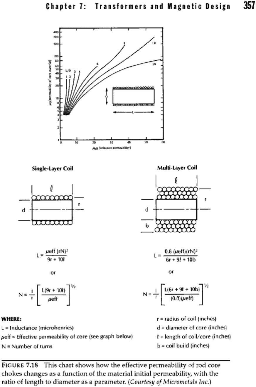
enter image description here

(I have this from Pressman, Billings, Morey, Switching Power Supply Design, 3rd Ed., Mcgraw-Hill (2009), but their source in turn comes from Micrometals, see: https://www.tme.eu/Document/82fc93ef93d05a020041f9203a13131a/MICROMETALS-Tseries.pdf page 24 (26). We also notice a discrepancy: they give multilayer radius as to the outer layer, but this is erroneous, it should be the average diameter.)

Note that the diagram doesn't extend to very high permeability such as ferrite provides; presumably the family of curves converge to a vertical asymptote, but it sure looks like the large L/D curves could reach a high value \$\mu_\textrm{eff}\$ on their way there.

Note also, the winding covers the whole core; in general, the inductivity (\$A_L\$ in µH/t2 or whatever) varies with the position of a given turn on the core, and turns don't couple perfectly with each other. The average figure, across all turns along the length of the rod, is as given here (or well, after dividing by \$N\$). You will get different results for short windings that don't cover the whole rod.

I don't have a close calculation for your particular materials and geometry, but a deeper lesson is perhaps this: magnetics, and fields problems in general, are often much more complicated to solve than you might expect given the simple materials needed to construct them; as such, either mere crude approximate solutions exist, or you basically have to go and measure the whole thing -- whether numerically in a field simulator, or empirically (the real deal).

\$\endgroup\$
2
\$\begingroup\$

Can someone please help my ignorance as to why measurements are not matching the theory/calculations.

May I remind you of the 2nd part of my answer to this question that you asked (Inductor not behaving even close to calculation). In that question you used a core with a relative permeability of 4000: -


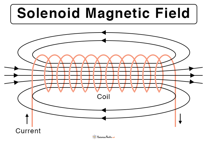
The other significant problem is that you have assumed a relative permeability of 4000 and, this just won't be the case. The magnetic field forms a closed loop from one pole of the iron rod, through the rod and back through air from the other pole to the first pole. See this diagram for instance: -

enter image description here

More than half the distance the field lines travel is through air. This means that the effective permeability is much closer to that of air and miles away from being 4000 (relative).


\$\endgroup\$
1
\$\begingroup\$

This is only a step above the iron rod permeability/inductance (77 micro-H for 35 turns).

Which is why 50 or 60 Hz transformers usually use laminated silicon steel, rather than ferrite.

Another thing to note is that length seems to matter here because when these ferrite rods are touched to one another, the inductance increases. This too may seem to disagree with the equation that indicates the inductance is turns per unit length.

Inductance is proportional to turns squared divided by length of coil. Adding to the length of the (non conductive) core does not decrease inductance, but increases it, by decreasing the amount of "empty space" near the coil. This however is not reflected in the formula you used, which assumes that the core and the coil are approximately the same length.

I seek to make a 10 H inductor by bundling the ferrite rods together

Assuming the coil is going to go around a bundle, rather than having multiple coils, one around each rod, the diameter of the coil will increase substantially when it encompasses a bundle. This will obviously affect/increase the inductance. I'm not sure you will easily attain 10 H, though. Typically for large inductances like that, the air gap is very small.

\$\endgroup\$
2
  • \$\begingroup\$ Thank you for your insight. So how do you supposed that small inductor (drastically smaller than my ferrite one) is 10 mH? \$\endgroup\$
    – zdanman
    Commented Nov 16, 2023 at 2:27
  • \$\begingroup\$ It has a very tiny air gap, if it has an air gap at all. The effective \$l\$ for that core is very small. \$\endgroup\$ Commented Nov 16, 2023 at 2:47

Your Answer

By clicking “Post Your Answer”, you agree to our terms of service and acknowledge you have read our privacy policy.

Not the answer you're looking for? Browse other questions tagged or ask your own question.