0
\$\begingroup\$

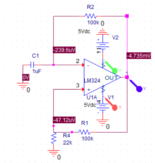
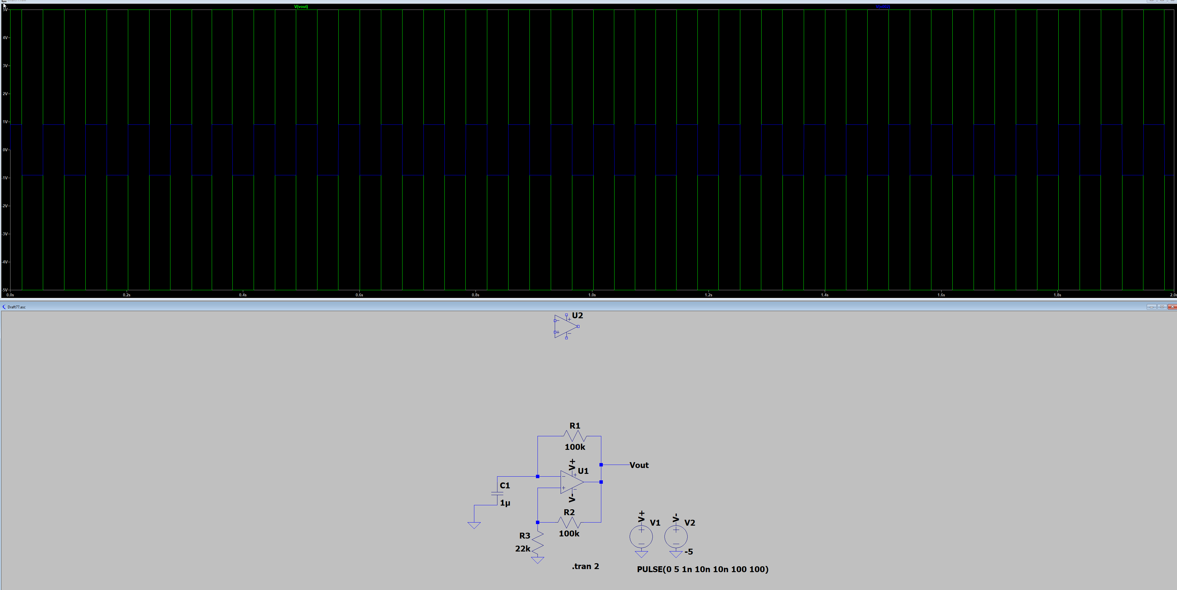
I'm trying to make a function generator using three op-amps, specifically the LM324. Right now I'm trying make the first square wave output using a DC input:

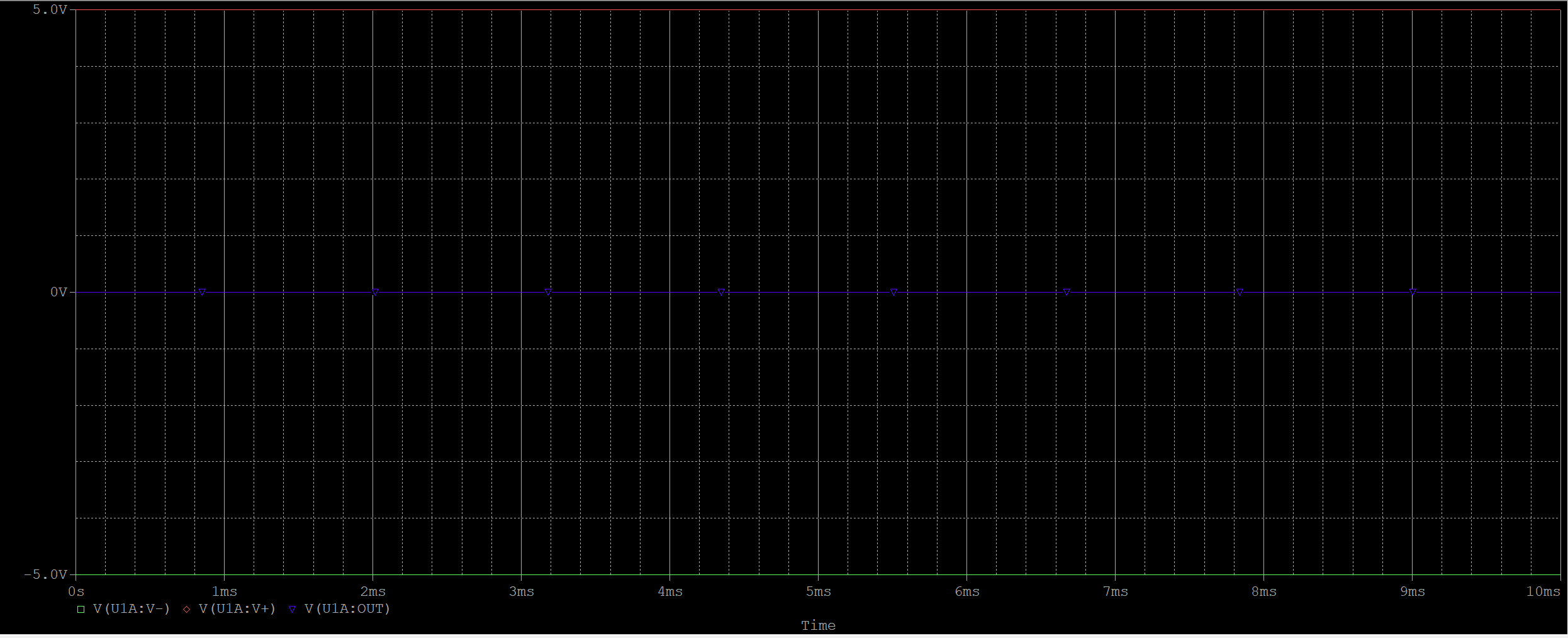
My OrCad simulation's output constant comes out as a zero, no matter what I do:

Attempt 1

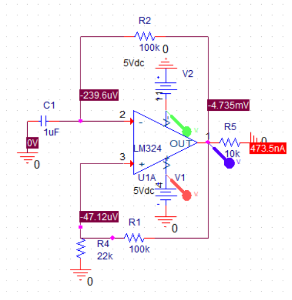
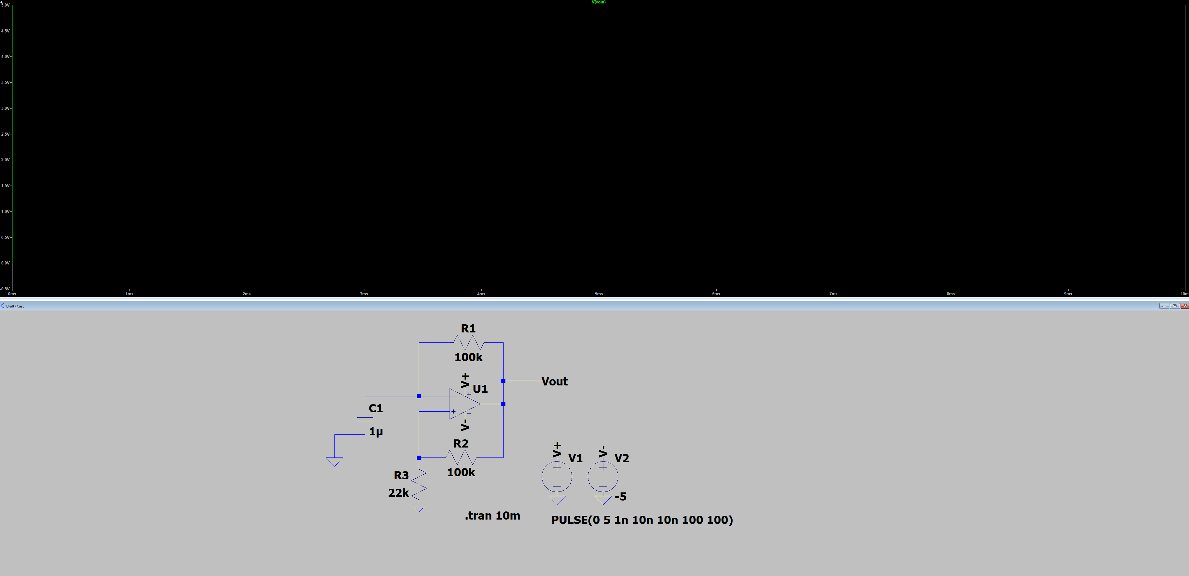
Attempt 2

Same results (no output)

What did I do wrong?

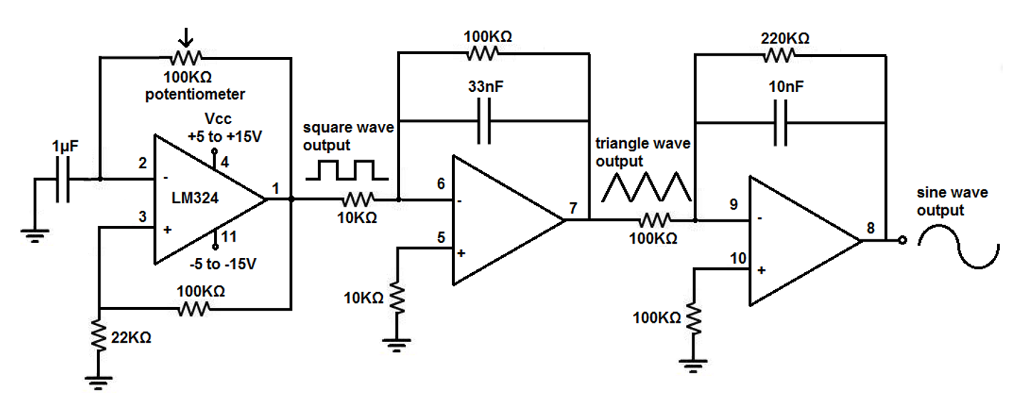
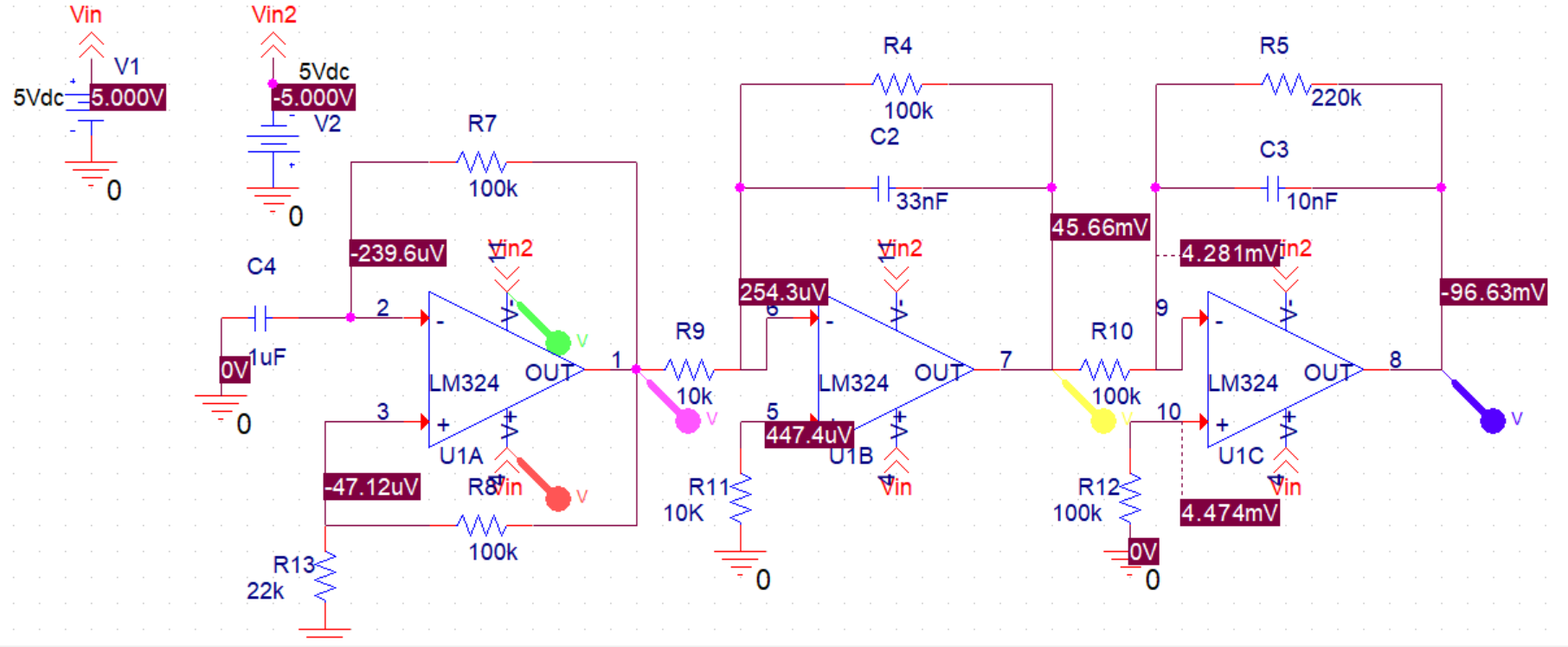
This is the full circuit I am trying to make:

Full diagram

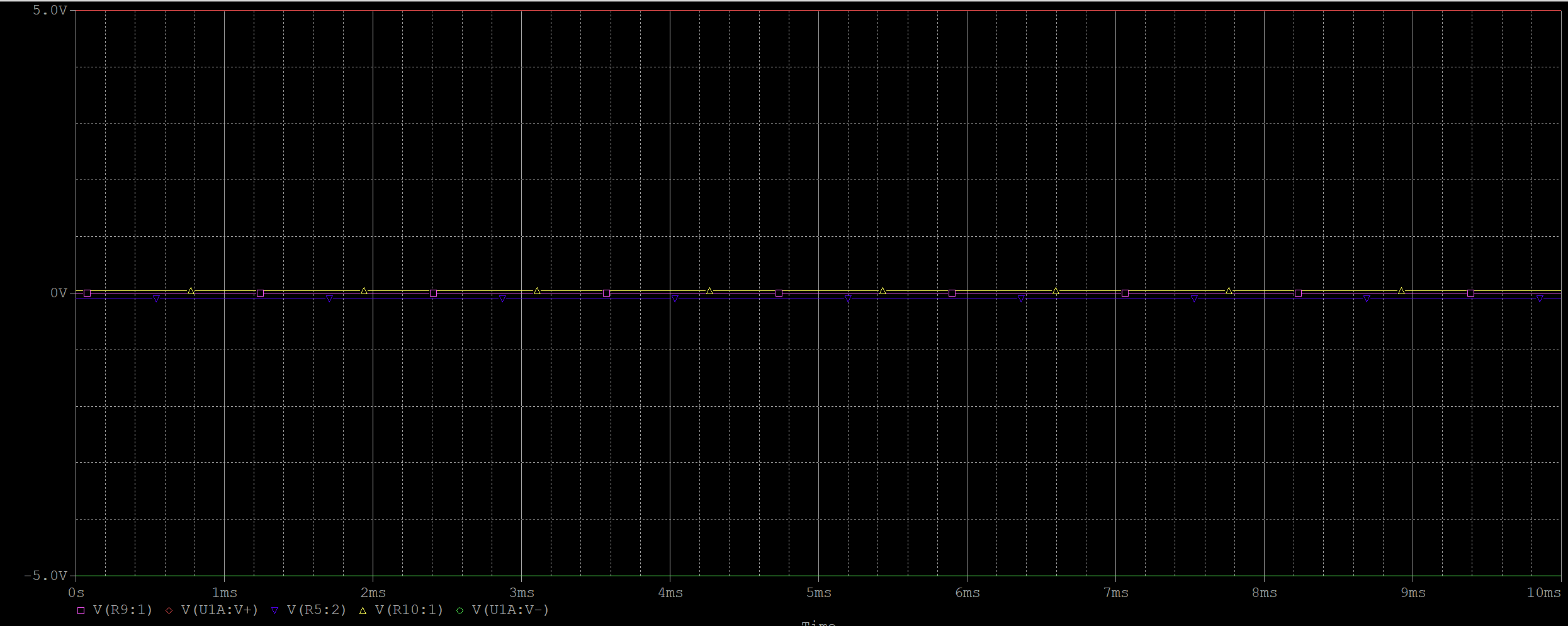
This is my attempt at it. Since my op-amp outputs keep coming out as a 0 I can not seem to produce any wave function at all:

My (full) attempt

(Full) attempt result

I feel like if I can just get the first op-amp result going then the rest of my op-amps will produce the desired graphs as well. (Unless I'm missing something.)

\$\endgroup\$
0

3 Answers 3

0
\$\begingroup\$

Seems that power supplies are not "wired" (no dots ?).
Your timebase is too short. It should be at least of 300 ms.
With my simulator, it start promptly. (2 ways).

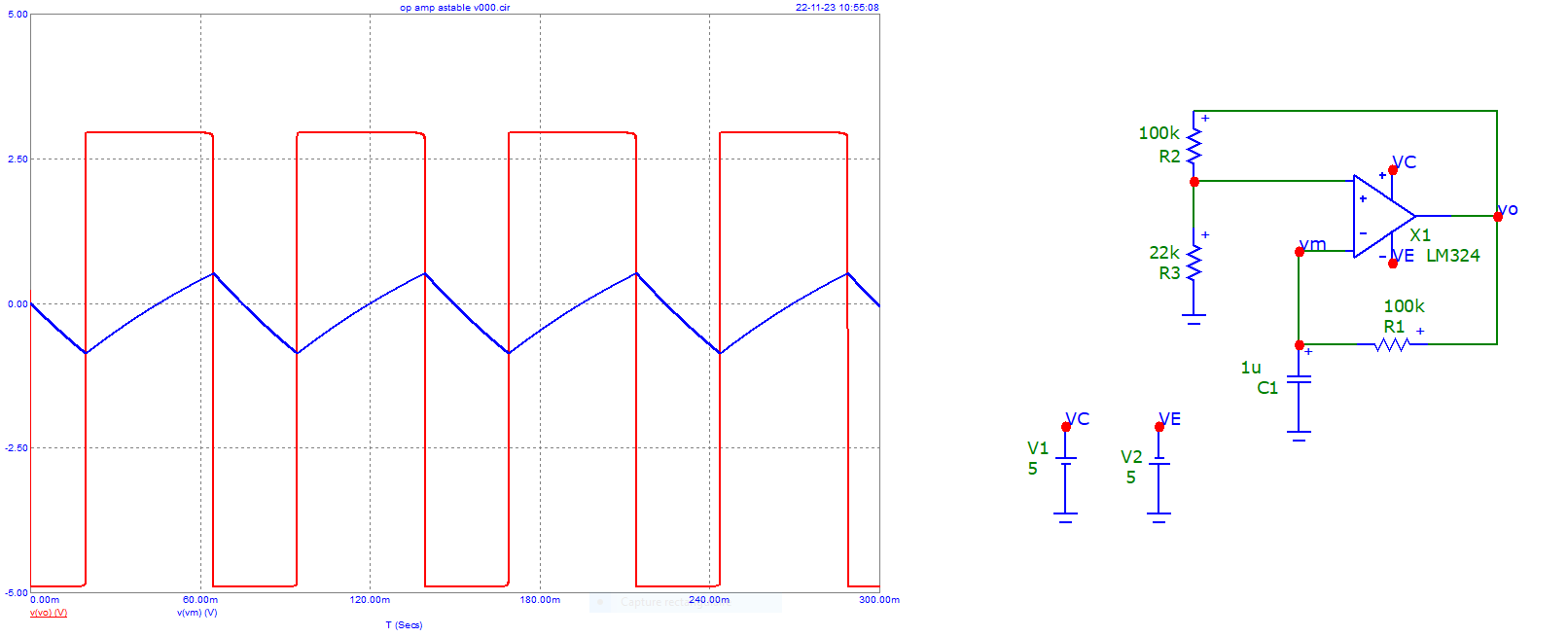
enter image description here

Here is the simulation of the circuit you are trying to make ...
Change of one resistor R4 (100k -> 10k).

enter image description here

\$\endgroup\$
2
  • \$\begingroup\$ It was! my timebase was way too short, thank you! My first Op-Amp is producing the desired square waves as you've shown, tho unfortunately the other two op amps are not producing the desired triangle and sine waves. If I may ask, how did you produce the triangle waves as shown above? \$\endgroup\$
    – Yeomaster
    Commented Nov 23, 2023 at 12:07
  • \$\begingroup\$ Triangle wave is inherently the base of the circuit (hysteresis). I will add another simulation showing the effects of the full circuit you are trying to make (change of frequency !) \$\endgroup\$
    – Antonio51
    Commented Nov 23, 2023 at 15:16
0
\$\begingroup\$

It is likely stuck in a quasi-stable state. It may eventually start oscillating if your simulation runs long enough.

Rather than that, try replacing one or both power supplies with sources that switch on just into the simulation.

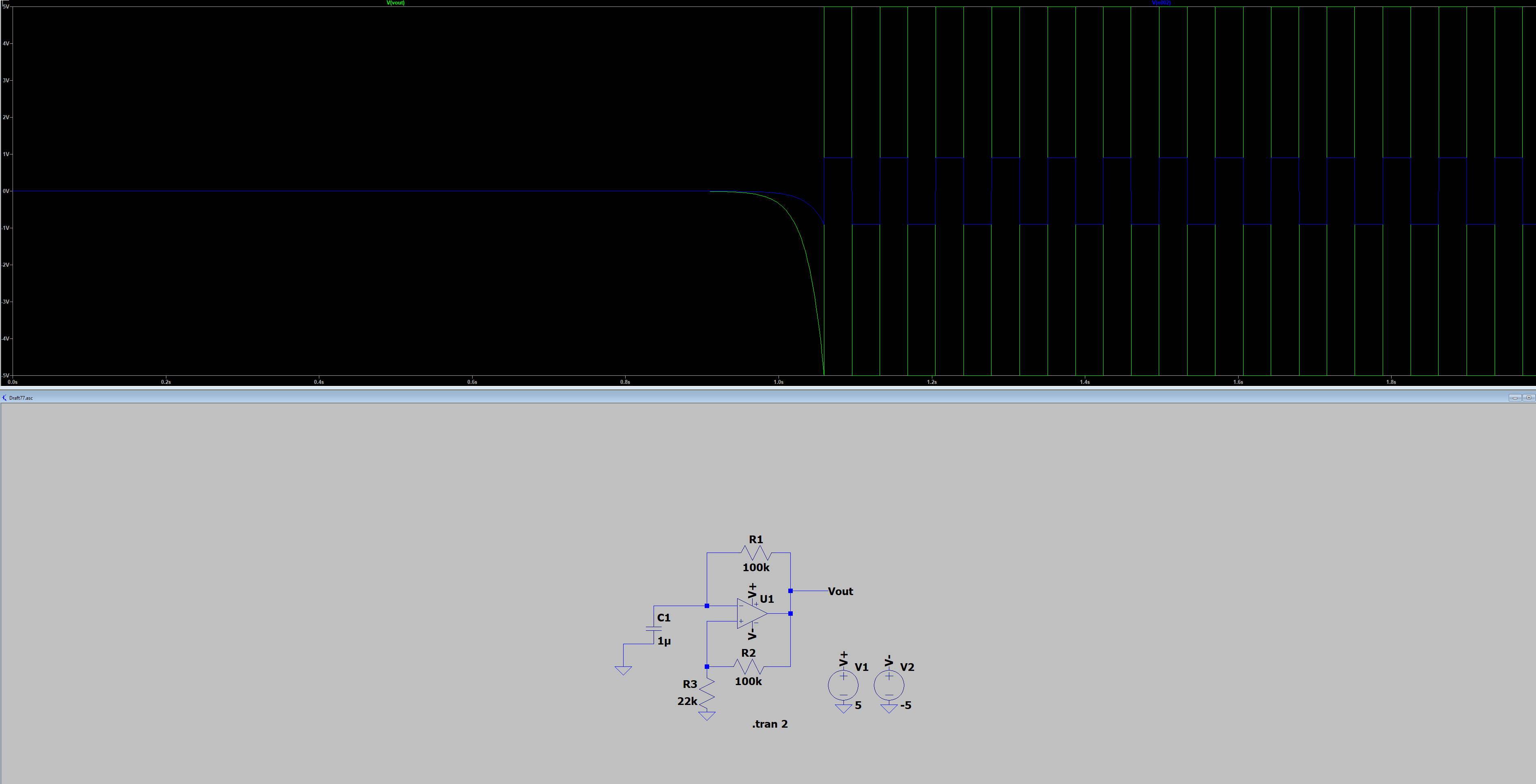
Here is an LTspice simulation with universal op-amp 2 (a single pole op-amp with one internal node, slew rate limit and output voltage and current limit):

enter image description here

It does not start oscillating until more than 1 second of simulated time has passed. The simulated output voltage starts at zero (a red flag with positive feedback) and only changes by a few microvolts during the first 500ms.

Here is the same circuit with the V+ supply delayed by one nanosecond after simulation starts:

enter image description here

The difference is obvious even with the short simulation time- the output immediately jumps to +5V rather than unnaturally sitting at 0V, though with 10ms of simulation you don't see the start of oscillation because it's too short for the 100ms time constant.

enter image description here

\$\endgroup\$
2
  • \$\begingroup\$ I agree that the oscillator needs a power-on pulse probably if one power supply voltage polarity turns on faster than the other power supply voltage polarity. \$\endgroup\$
    – Audioguru
    Commented Nov 23, 2023 at 18:04
  • \$\begingroup\$ @Audioguru SPICE calculates an initial condition before starting the transient simulation based on DC supply voltages so the op-amp is left balanced on knife-edge at the very beginning. Depending on the op-amp model specifics it can take a long time to come out of that state. See above edits. It's not usually a problem with op-amps used as op-amps rather than comparators. Some suggest using -uic (skip initial operating point solution), but I think that's not ideal. \$\endgroup\$ Commented Nov 23, 2023 at 18:34
0
\$\begingroup\$

In your circuit, the triangle wave amplitude will vary inversely with frequency; as you vary the freq of the squarewave oscillator, the integrator has more or less time to ramp, changing the resulting peak-to-peak amplitude.

There is a better configuration of three opamps for what you are trying to do. The first amp is a comparator with hysteresis. One input is the reference and one is the output of the integrator. As you vary R9 (the integrator input), the integration time changes but the amplitude remains constant, determined only by the comparator.

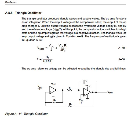
Here is a screen grab from way back. It looks like part of a TI app note. It shows the comparator reference as Vcc/2. If you replace this with a pot, changing the pot wiper voltage changes the triangle wave symmetry.

enter image description here

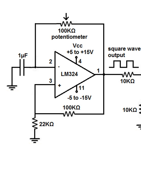
Here is another example of the square and triangle parts.

http://www.piclist.com/images/www/hobby_elec/e_ckt16.htm

\$\endgroup\$

Your Answer

By clicking “Post Your Answer”, you agree to our terms of service and acknowledge you have read our privacy policy.

Not the answer you're looking for? Browse other questions tagged or ask your own question.