0
\$\begingroup\$

Consider an RLC circuit. I have found much questions related to RLC's asked before, but I think I need to educate myself a bit more. I have the general idea about critical damping, over-damping and under-damping. However, the issue is, why doesn't my output in an oscilloscope match with the expected one from the equation for the case of underdamping.
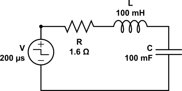
schematic

simulate this circuit – Schematic created using CircuitLab

Here, a step voltage \$V_s=0.5V\$ has been applied in the circuit. Here, we have: $$\alpha=\frac{R}{2L}=8$$ $$\omega_0=\frac{1}{\sqrt{CL}}=10$$ excluding the units. Therefore, the damping frequency is:

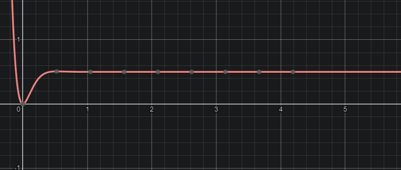
$$\omega_d^2=\sqrt{\alpha^2-\omega_0^2}=-36$$ The series circuit about has \$\alpha<\omega_0\$ which means it is underdamped. For such a system the voltage across the capacitor is governed by the equation: $$v_c(t)=V_s+(A_1\cos{\omega_d t}+A_2\sin{\omega_d t})e^{-\alpha t}$$ To solve the equation, I have considered two initial conditions. The first is that, capacitor voltage must be 0 at \$t=0^+\$ since it cannot abruptly change its voltage. Second, the rate of change of voltage just at that time is \$0\$, since inductor does not allow change of current just at \$t=0^+\$. Therefore, I have in my hand: $$v_t(0^+)=0$$ and $$\frac{di(0^+)}{dt}=C \frac{dv_c(0^+)}{dt}=0$$ Plugging this two conditions into the equation, I found out \$A_1=-0.5\$ and \$A_2=-\frac{2}{3}\$. The equation, so becomes: $$v_c=\frac{1}{2}+\left(-\frac{1}{2}\cos(6t)-\frac{2}{3}\sin(6t)\right)e^{-8t}$$ Everything goes well up to this. As I plug this equation in desmos, what I get is something like this: enter image description here
However, this shall not be the case. An underdamped circuit usually have the response: enter image description here
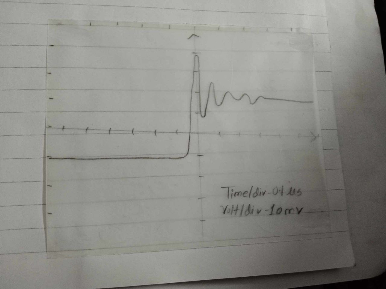
Now, there are few issues that need to be solved. First, what's incorrect in my equation. I presume that some of my initial conditions have gone wrong. Second, if the oscilloscope is correct [and I surely know it is], then what line am I suppose to consider as \$t=0\$ line? I need to properly place the graph in the tracing paper, so that my data, extracted from here, is accurate.

\$\endgroup\$
6
  • 1
    \$\begingroup\$ I don't follow your question. If taking the voltage across the capacitor, then the system has a damping factor of 0.8 and an omega of 10. While it's technically under-damped, it most certainly will not have an output looking like your 2nd diagram! You say "why doesn't my output in an oscilloscope match with the expected one from the equation" and show a 2nd diagram that has nothing to do with this system. The first one looks more like what it should look like (run too long, though -- limit the x-axis to maybe 1 s?). So what's up? \$\endgroup\$ Commented Nov 25, 2023 at 10:56
  • \$\begingroup\$ @periblepsis But underdamped circuits do show responses like that, don't they? The second diagram is also of underdamped response but with a different magnitude of resistors, capacitors and inductors, having the same DC input. \$\endgroup\$
    – M.Riyan
    Commented Nov 25, 2023 at 11:46
  • \$\begingroup\$ They do. But not in the case you provided. Notice that you specified specific values? Also, your approach is not sufficiently robust. You actually should come up with a general solution that involves \$A_1\$, \$A_2\$, and \$A_3\$. (for inhomogeneous vs homogeneous reasons.) That doesn't mean that the particular part and general part don't reduce this down. They do. But your approach isn't rigorous. It's "fly by night" so to speak. Are you interested in a general exposition (sniping me, long story)? Or just a specific answer using your specific values? \$\endgroup\$ Commented Nov 25, 2023 at 11:50
  • \$\begingroup\$ @periblepsis A general exposition would do. \$\endgroup\$
    – M.Riyan
    Commented Nov 25, 2023 at 12:27
  • \$\begingroup\$ That takes time. Less if kept terse. But still more time. Asking a lot. \$\endgroup\$ Commented Nov 25, 2023 at 14:52

1 Answer 1

1
\$\begingroup\$

The series circuit about has α <\$ω_0\$ which means it is underdamped.

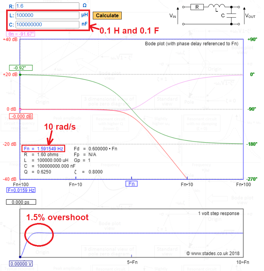
It is underdamped (\$\zeta = 0.8\$) but significantly, you thought that its response will be far more underdamped than what it is. Here is a view of my RLC low-pass calculator with your values plugged-in: -

enter image description here

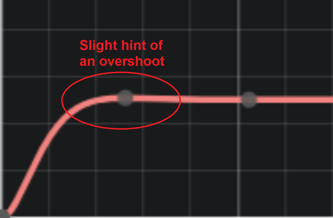
There are small signs of overshoot (and ringing) but the major overshoot peak is only 1.516 % higher than the input step amplitude. I expect that if you analysed your scope shot more carefully, you will see the same: -

enter image description here

You also made this rookie error: -

Therefore, the damping frequency is: \$\omega_d^2=\sqrt{\alpha^2-\omega_0^2}=-36\$

The error you made was to believe that a negative sign inside a square root can be transferred to the outside of the square root as a negative sign. The square toot of -1 is actually \$j\$ hence, your damped resonant frequency is \$j6\$.

\$\endgroup\$
2
  • \$\begingroup\$ I understand that. But can you help me with the second question? Why does oscilloscope have a negative voltage across the capacitor at a point. What do I consider as the t=0 line? \$\endgroup\$
    – M.Riyan
    Commented Nov 25, 2023 at 12:10
  • \$\begingroup\$ @M.Riyan I didn't see the negative voltage in the picture that you refer to. That wasn't mentioned in your original question. \$\endgroup\$
    – Andy aka
    Commented Nov 25, 2023 at 12:24

Your Answer

By clicking “Post Your Answer”, you agree to our terms of service and acknowledge you have read our privacy policy.

Not the answer you're looking for? Browse other questions tagged or ask your own question.