0
\$\begingroup\$

I'd like to ask for help with calculating a gain of a PWM modulator using a triangle wave.

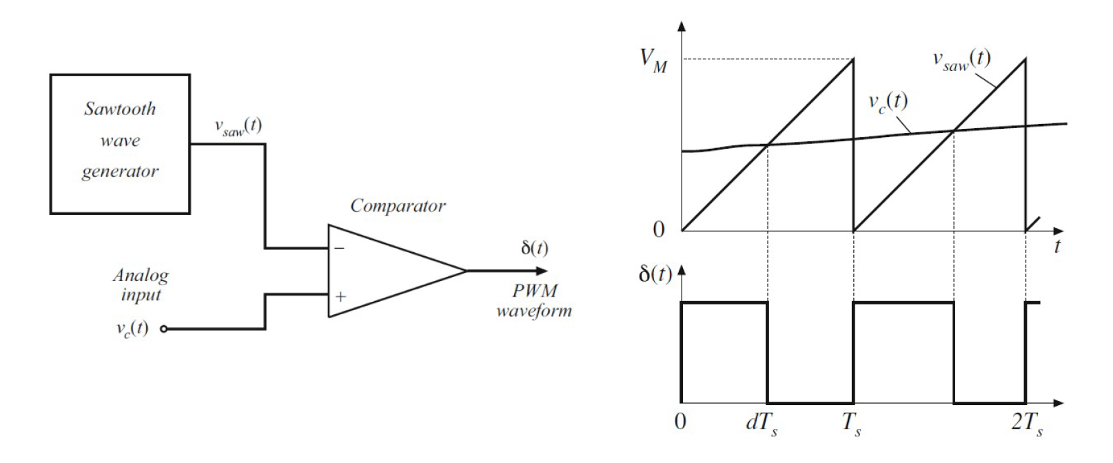
I know how to calculate a gain in case with a sawtooth carrier with turning-on at the start of cycle.

enter image description here

and


The DC gain equals:


and the AC gain is the same:


Where is an amplitude of the sawtooth wave and these realtions are valid for .


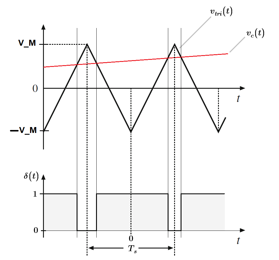
Next, I would like to calculate the gain for the same configuration but with triangle carrier instead of the sawtooth.

enter image description here enter image description here

And here is my first question. Can I assume that the control signal is much slower than the carrier? I mean that I assume that the control signal has the same level at the beginning of the pulse and at the end? It can simplify a lot calculating the gain cuz it will be symetrical around the peak of carrier.

Could you help me with the calculations? I'm really confused how to start...

\$\endgroup\$
4
  • \$\begingroup\$ Please start by defining the gain you want to calculate in terms of input signal and output signal. \$\endgroup\$
    – Andy aka
    Commented Nov 26, 2023 at 17:12
  • \$\begingroup\$ The small-signal gain \$\frac{d(s)}{V_c(s)}\$ remains the same whether the ramp is a sawtooth or a triangle. The duty ratio is a discrete value and if you simulate via SIMPLIS the two configurations, sawtooth and triangle, give the same operating point (static duty ratio) as well as the small-signal gain, \$\frac{1}{V_p}\$. \$\endgroup\$ Commented Nov 26, 2023 at 17:25
  • \$\begingroup\$ @VerbalKint I don't think so that the answer 1/V_M is right. Simple check with values does not give the proper answer. I did similar calculations like above with assumption that the control signal V_c at the first and second interscetion is the same (I don't know if I should do it?). I got D=(V_M+V_C)/(2*V_M), and the AC gain dd(t)/dv_c(t)=1/(2*V_M) what gives right results when substituted with couple of random values. What intrigues me most is whether the assumption that in both intersections the control signal can be approximated with the same value is correct? \$\endgroup\$
    – Bart
    Commented Nov 26, 2023 at 18:25
  • \$\begingroup\$ If time permits, I will post a simple simulation setup using SIMPLIS which can extract the transfer function in a second. You can easily do the experiment with the demo version Elements. \$\endgroup\$ Commented Nov 26, 2023 at 19:44

1 Answer 1

0
\$\begingroup\$

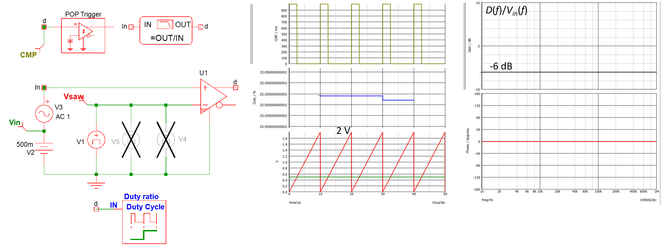
I ran a few simulations with different types of artificial ramps to check the transfer function of the pulse-width modulator (PWM) block. First, we start with the naturally sampled modulator, driven by a classical sawtooth, here is with a 2-V peak amplitude:

enter image description here

SIMPLIS is well suited for extracting the transfer function of this switching circuit. The small-signal gain is 0.5 or -6 dB.

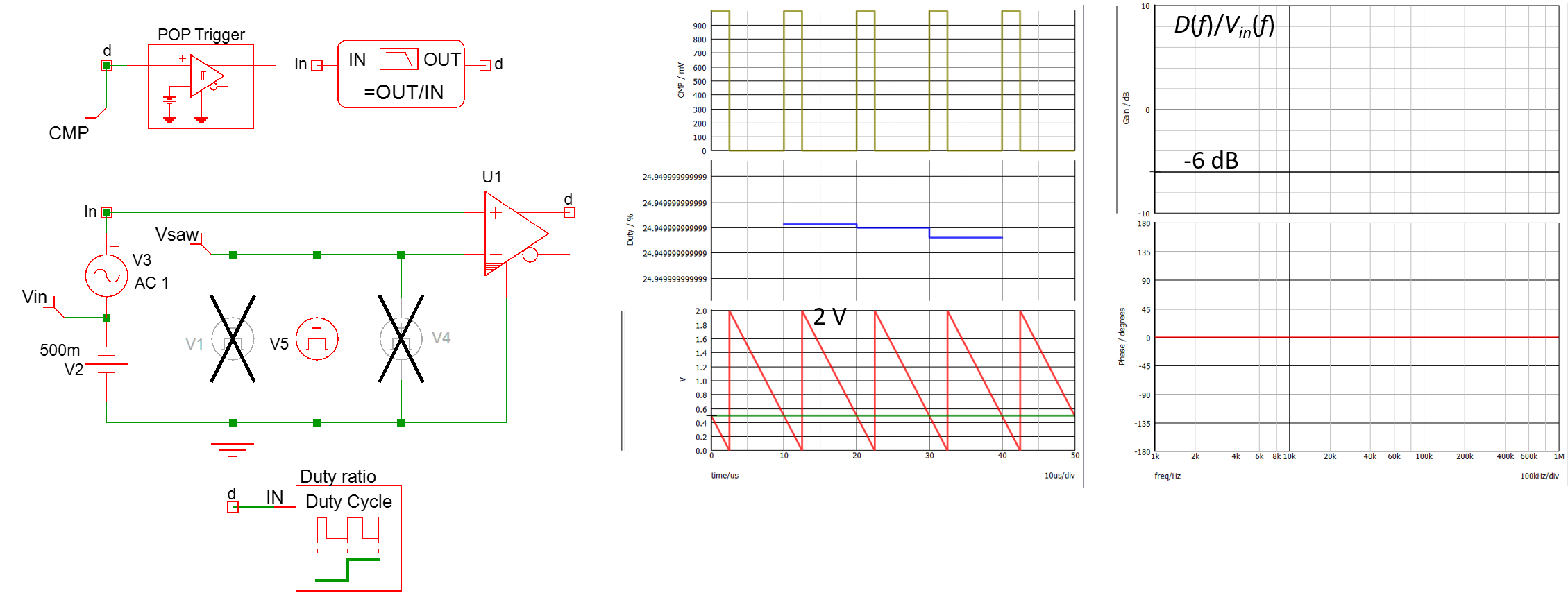
The second circuit is a leading-edge modulator (the previous was a trailing edge type) and the attenuation remains the same at 6 dB:

enter image description here

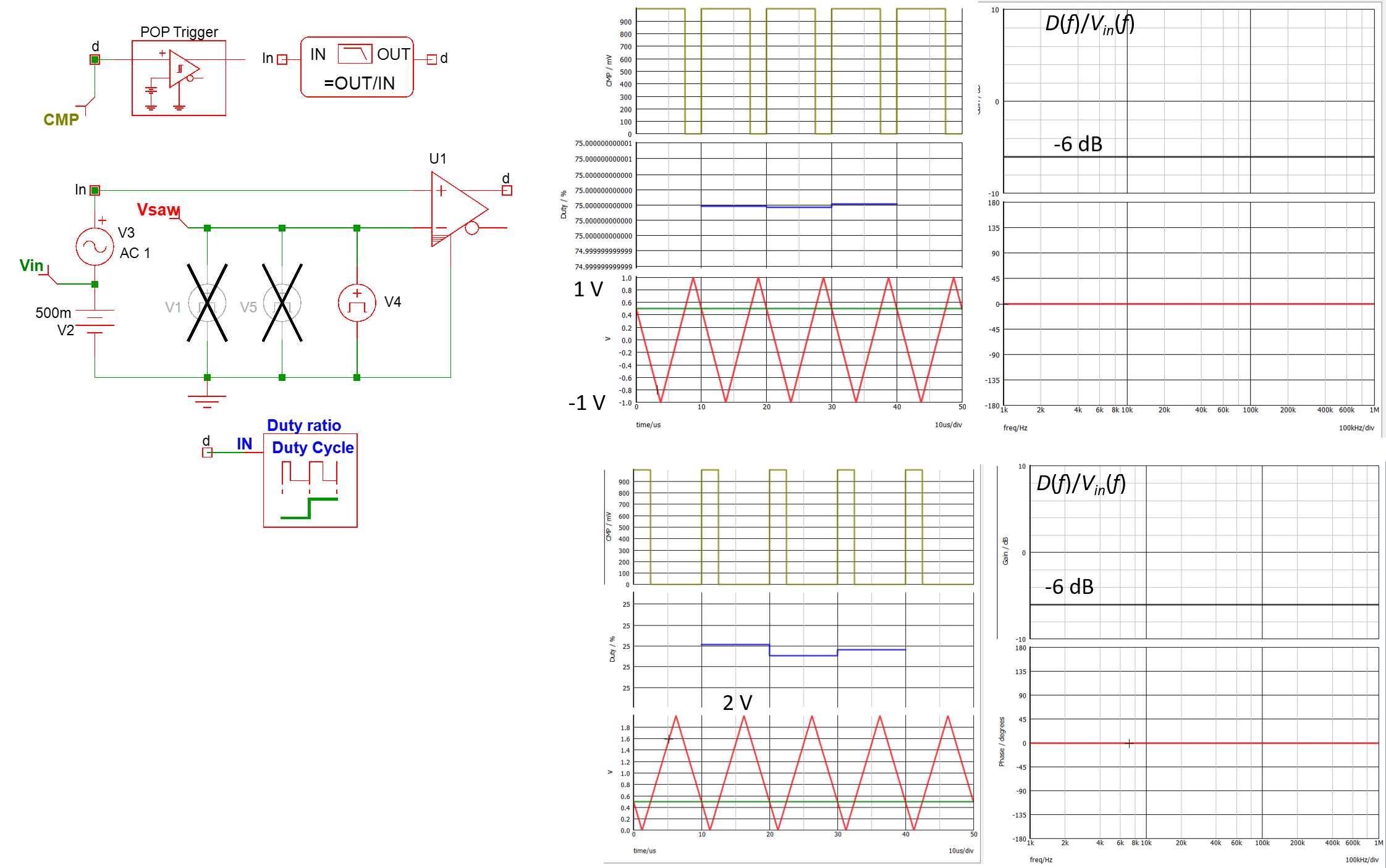
Then I used two triangular waveforms, one starting from 0 to 2 V and another one from -1 to 1 V:

enter image description here

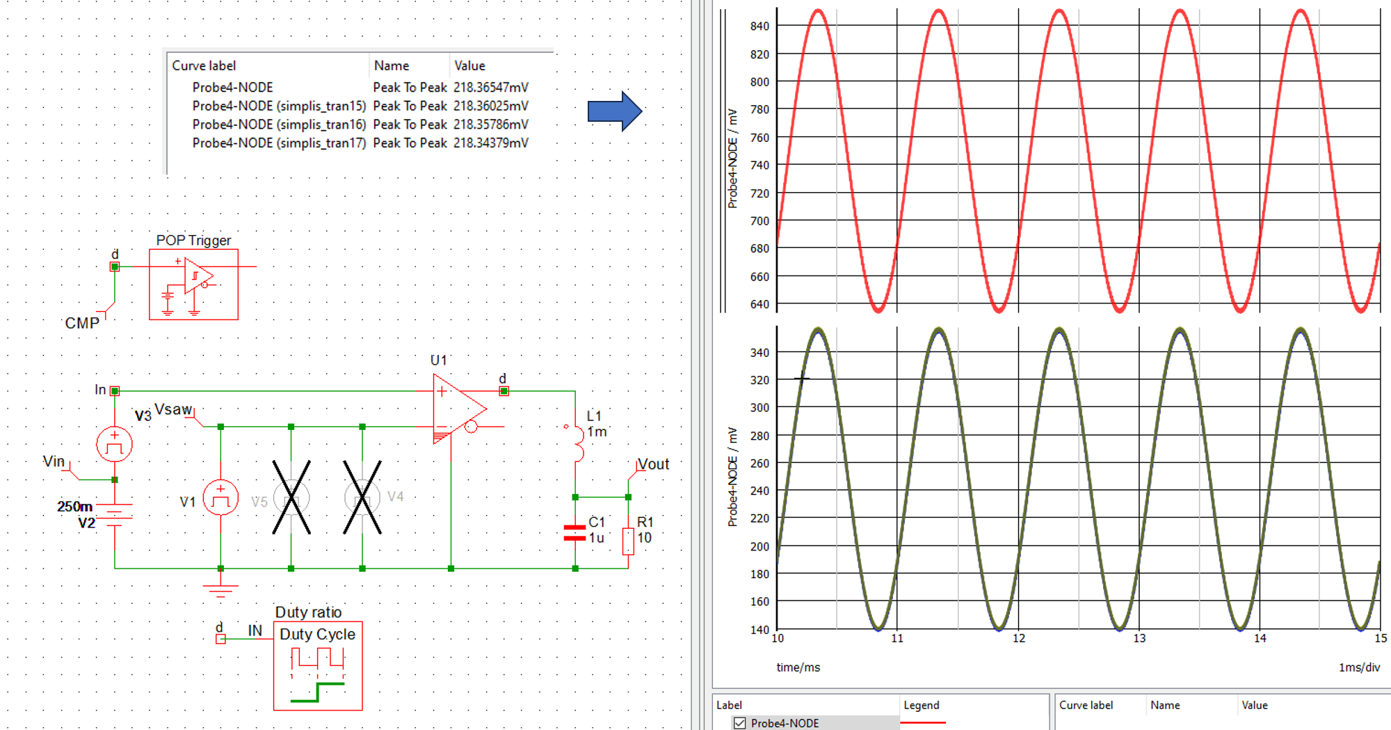
Finally, I have added a low-pass filter and did replace the ac source by a 1-kHz sinewave. The demodulated signal has been plotted with the 4 different ramp voltages and the peak-to-peak values for the 4 resulting output voltages are identical:

enter image description here

\$\endgroup\$
6
  • \$\begingroup\$ Thank you for your effor. Interesting, I did the same analysis in PLECS and I got gain -12 dB (0.25 V/V) what matches with my calculation 1/(2*V_M) for the ramp triangle -2V to 2V. When I applied -1V to 1V I got -6dB (what matches your result for this configuration). Could you run the simulation for -2V and 2V? \$\endgroup\$
    – Bart
    Commented Nov 26, 2023 at 23:26
  • \$\begingroup\$ Btw, do I speak with you Basso :D? \$\endgroup\$
    – Bart
    Commented Nov 26, 2023 at 23:34
  • \$\begingroup\$ Yes, this is me typing. The gain for a -2/2-V peak is -12 dB as confirmed by SIMPLIS. \$\endgroup\$ Commented Nov 27, 2023 at 6:21
  • \$\begingroup\$ @Bart, if you think my reply answered your question, thank you to acknowledge it as a valid answer. Cheers, Chris. \$\endgroup\$ Commented Nov 29, 2023 at 15:43
  • \$\begingroup\$ Hi Verbal Kint, Thank you for your time and help! The answer matches my calculations. I'm so sorry that I'm responding late but I was struggling with multilevel inverters and was 100% busy. Btw I would like to tank you as well for your books Chris! I sent you an invitation in Linkedin :D \$\endgroup\$
    – Bart
    Commented Nov 29, 2023 at 19:55

Your Answer

By clicking “Post Your Answer”, you agree to our terms of service and acknowledge you have read our privacy policy.

Not the answer you're looking for? Browse other questions tagged or ask your own question.