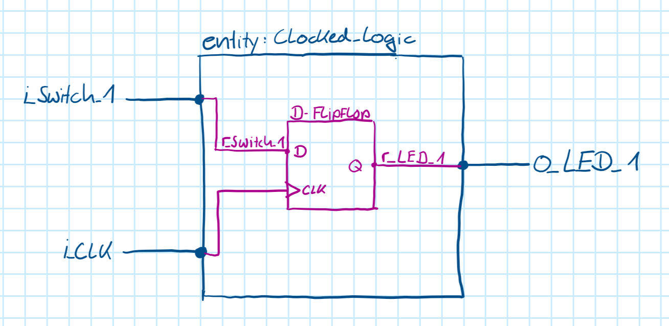
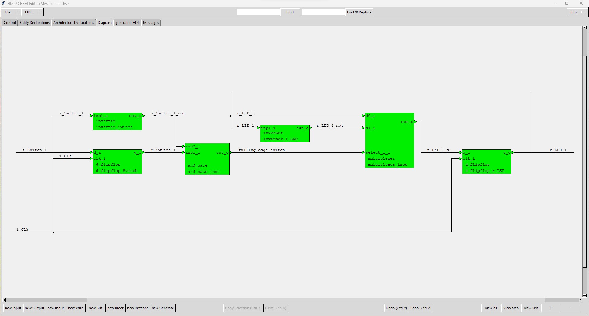
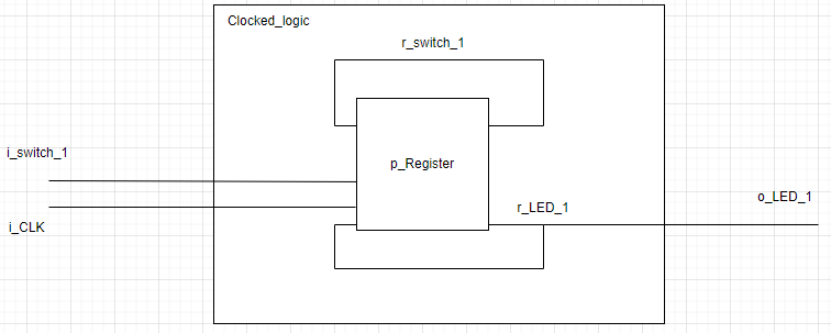
The following code is given. My task involves drawing a visual hardware representation that outlines the modules, their associated ports, and the interconnecting signals. Check out my solution below. Am I on the right track?
flipflop.vhdl:
library ieee;
use ieee.std_logic_1164.all;

entity Clocked_Logic is

    port (i_Clk      : in  std_logic;
          i_Switch_1 : in  std_logic;
          o_LED_1    : out std_logic);

end entity Clocked_Logic;


architecture RTL of Clocked_Logic is

    signal r_Switch_1 : std_logic := '0';
    signal r_LED_1    : std_logic := '0';

    begin

        -- this clocked-sequential process starts when i_Clk state change
        -- the sensitivity list contains only i_Clk
        p_Register: process (i_Clk) is
        begin

            if rising_edge(i_Clk) then

                r_Switch_1 <= i_Switch_1;

                if i_Switch_1  = '0' and r_Switch_1 = '1' then

                    r_LED_1 <= not r_LED_1;

                end if;

            end if;

        end process p_Register;

        o_LED_1 <= r_LED_1;

end architecture RTL;
My solution:


ghdl\$\endgroup\$